Process for determining the direction of the earth's magnetic field

Inactive Publication Date: 2000-01-04
LEICA GEOSYSTEMS AG
View PDF6 Cites 107 Cited by
  • Summary
  • Abstract
  • Description
  • Claims
  • Application Information

AI Technical Summary

Problems solved by technology

It is therefore unnecessary to use a magnetic

Method used


Image

  • Process for determining the direction of the earth's magnetic field
  • Process for determining the direction of the earth's magnetic field

Examples


Embodiment Construction

As early as the 19th century, Poisson addressed the problem of how to measure the magnetic field which is actually present if a magnetometer is set up in a system which itself has magnetic components. Poisson's formula, which describes this situation, expresses the idea that, in such a case, the magnetic field which is measured is a linear function of the field that is actually present, and an affine transformation is thus involved. In conjunction with this, reference may be made to the abovementioned U.S. Pat. No. 4,686,772, column 2, lines 26 to 30.

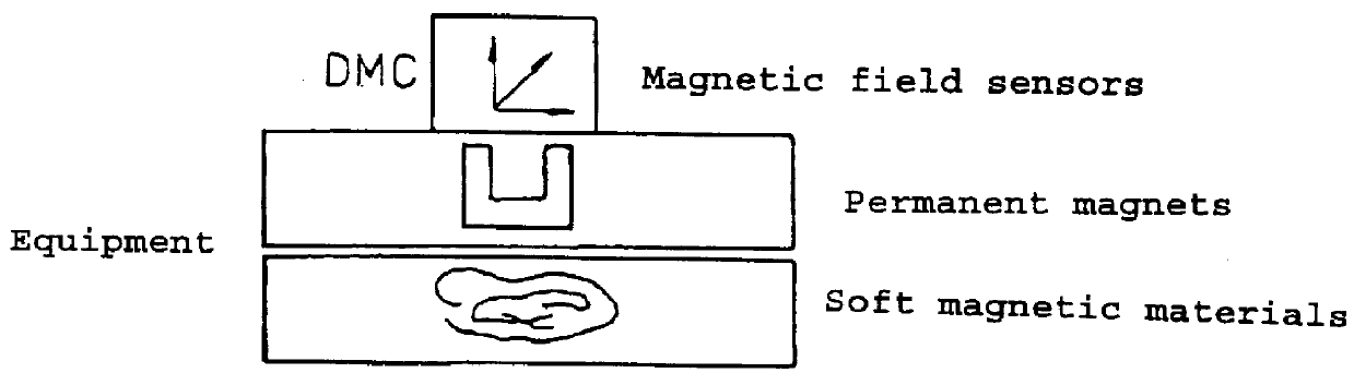
For the general case, it can be stated that the measured magnetic field is composed of the soft-magnetically distorted Earth's magnetic field at the measurement site and of a hard-magnetic component. The soft-magnetically distorted Earth's magnetic field involves magnetism induced by the Earth's magnetic field. The hard magnetic component comprises, for example, magnetic fields which are constant at the site of the magnetometer and are ...


PUM


Abstract

PCT No. PCT/EP97/00583 Sec. 371 Date Nov. 10, 1997 Sec. 102(e) Date Nov. 10, 1997 PCT Filed Feb. 10, 1997 PCT Pub. No. WO97/34125 PCT Pub. Date Sep. 18, 1997A method for determining the direction of the Earth's magnetic field, which may be interfered with by magnetic materials built into equipment and by electric currents, using an electronic magnetic compass which contains three magnetic field sensors and two devices for measuring inclination is provided. The electronic magnetic compass is arranged in N different spatial positions, in each of these N positions, the inclination sensor signals and the magnetic field sensor signals being measured and inclination values and magnetic field values being determined from these signals. On the basis of these inclination values and magnetic field values, the magnitude of the Earth's magnetic field vector is determined using the vector equationconst=bg=bEsin(i)=gTL(bE)=gTm(bmes-bo)with N having to be at least equal to the number of parameters to be determined in the vector equation.

Description

1. Field of the InventionThe invention relates to a method for determining the direction of the Earth's magnetic field, which may be interfered with by magnetic materials built into equipment and by magnetic fields produced by electric currents, using an electronic magnetic compass which contains three magnetic field sensors and two devices for measuring inclination.2. Description of the Related ArtU.S. Pat. No. 4,686,772 discloses an electronic magnetic compass which, for example, is intended to be used to determine the heading of a tank. The tank has two iron bodies, namely the turret and the vehicle body, which can rotate relative to one another about a vertical axis. The magnetic compass is arranged in the vehicle body and comprises a non-pendulous triaxial magnetometer which outputs electrical magnetic field signals that represent the three magnetic field components at the site of the magnetometer. Two inclination sensors are provided, which output electrical signals that repre...

Claims


Application Information

Patent Timeline
IPC IPC(8): G01C17/28G01C17/00G01V3/40G01C17/38
CPCG01C17/28G01V3/40G01C17/38
Inventor GNEPF, SILVIOWEILENMANN, JUERG
Owner LEICA GEOSYSTEMS AG
Why Eureka
Try Eureka