
A vehicle/traffic flow detection method based on a three-axis magnetoresistive sensor

A technology of traffic flow detection and three-axis magnetic resistance, which is applied in the field of intelligent transportation, can solve problems such as being easily affected by the surrounding environment, high cost of video detectors, and reduced detection accuracy, so as to improve anti-interference ability, overcome drift problems, and resist strong interference effect

Inactive Publication Date: 2011-12-21
BEIHANG UNIV
View PDF2 Cites 49 Cited by
  • Summary
  • Abstract
  • Description
  • Claims
  • Application Information

AI Technical Summary

Problems solved by technology

Toroidal coils have high precision and simple structure, but they cannot be widely used due to the need to dig roads for installation and maintenance; video detectors are expensive and have low detection accuracy at night and in bad weather environments; microwaves are mostly used for vehicle speed detection on high-speed roads, and are easy to install , but it is easily affected by the surrounding environment and is not easy to promote
[0004] In recent years, the vehicle / traffic flow detection method based on the magnetoresistive sensor has received extensive attention, but the existing research on the vehicle / traffic flow detection based on the magnetoresistive sensor is limited by the use of single-axis or dual-axis sensors with analog signals. , the vehicle / traffic flow detection algorithm is mainly based on the Z-axis component of the vertical component of the geomagnetic field, and also based on the magnetic declination D; since the magnetic sensor is installed in the middle of the lane, if the vehicle passes directly above the magnetic sensor, the above method can obtain better Good effect, but if the vehicle passes by the magnetic sensor, the magnetic field is farther away from the Z axis and closer to the X or Y axis. At this time, the Z axis signal will decay linearly so that the signal cannot be detected, while the X or Y axis magnetic field It will increase linearly, so the detection accuracy based on the Z axis will decrease; and the existing method of detecting sensor placement needs to ensure that the Z axis is perpendicular to the vehicle, which is difficult to achieve in practical applications and will affect the detection accuracy; in addition, the current detection method It cannot solve the problem of sensor signal output drift when vehicles pass by end to end continuously, resulting in a decrease in detection accuracy

Method used


Image

  • A vehicle/traffic flow detection method based on a three-axis magnetoresistive sensor
  • A vehicle/traffic flow detection method based on a three-axis magnetoresistive sensor
  • A vehicle/traffic flow detection method based on a three-axis magnetoresistive sensor

Examples


Embodiment Construction

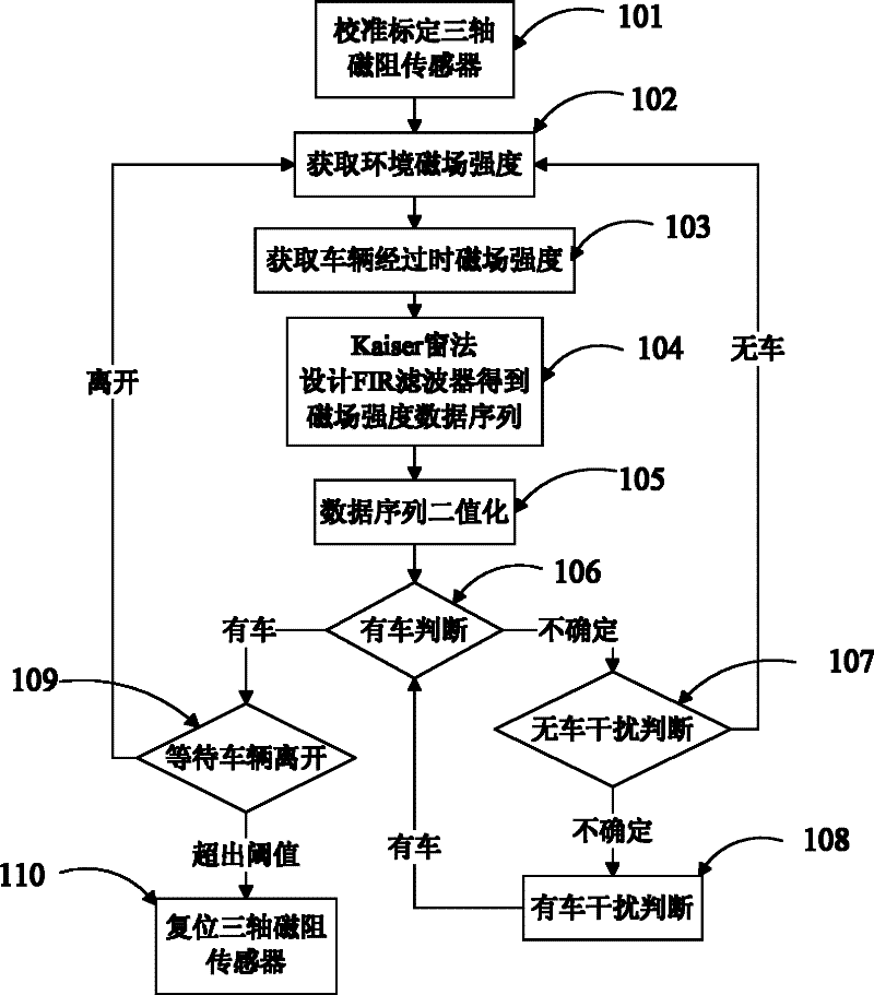
[0037] Such as figure 1 Shown, method of the present invention comprises the following steps:

[0038] Step 1. Calibrate or calibrate the three-axis magnetoresistive sensor used in step 101;

[0039] Step 2. In step 102, use the calibrated or calibrated three-axis magnetoresistive sensor to obtain the synthetic environmental magnetic field strength of the X, Y, and Z axes

[0040] Step 3. In step 103, use the calibrated or calibrated three-axis magnetoresistive sensor to obtain the magnetic field strength generated when the vehicle passes by the X, Y, and Z three-axis synthesis

[0041] Step 4, utilize Kaiser window method to design FIR filter in step 104, to the magnetic field intensity obtained in step 3 and the magnetic field strength obtained in step 2 difference Perform filtering processing to obtain the data sequence f(k);

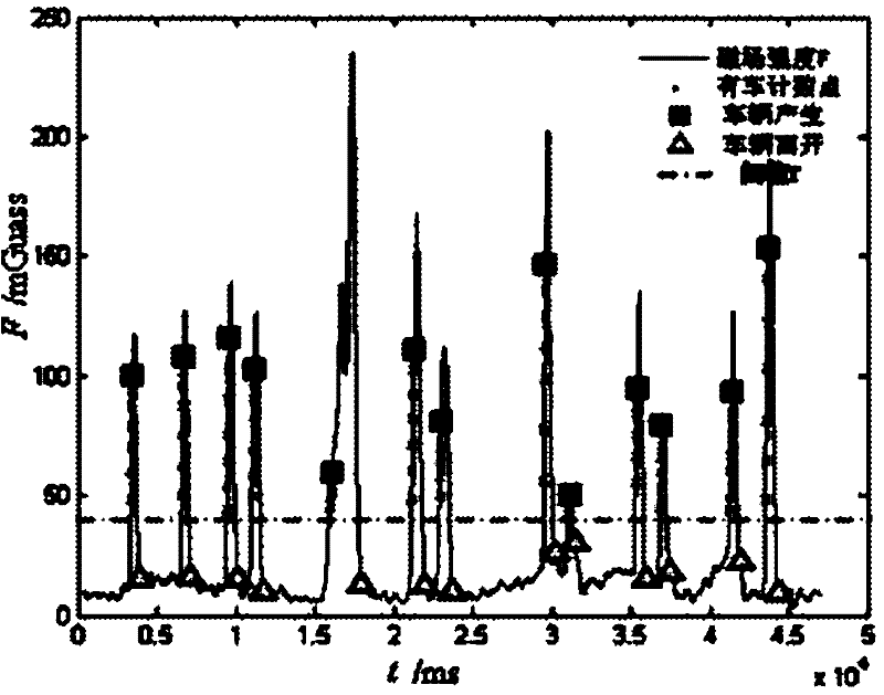
[0042] Step 5. Binarize f(k) in step 105: set the vehicle threshold T according to the test data, and the range of T is usually 5≤T≤45. ...


PUM


Abstract

The invention relates to a vehicle / vehicle flow detection method based on a three-axis magnetoresistive sensor, comprising the following steps: calibrating or calibrating the three-axis magnetoresistance sensor; obtaining the environmental magnetic field strength when there is no car, and obtaining the magnetic field strength when there is a car passing by; using Kaiser The FIR filter is designed to filter the measured magnetic field strength data to obtain the data sequence; the data sequence is binarized; whether there is a car is judged; when there is no car, interference is judged; when there is a car, interference is judged; the vehicle leaves the judgment; after the vehicle is judged The software forcibly resets the three-axis magnetoresistive sensor. It is characterized in that the method integrates the three-axis magnetic field information, which can fully reflect the disturbance information of the geomagnetic field when the vehicle passes by, the sensor can be placed arbitrarily, and the software reset method can effectively overcome the signal drift of the magnetic resistance sensor generated when the vehicle passes continuously Problems, through the judgment of vehicle entry, interference, and vehicle departure, it can ensure high detection accuracy and strong anti-interference ability. This method is easy to implement and is suitable for vehicle / traffic flow detection on traffic roads, bridges, squares, tunnels, etc. It can also be used in Vehicle detection in the parking lot for intelligent management.

Description

technical field [0001] The invention relates to a vehicle / traffic flow detection method in the field of intelligent transportation and the like, in particular to a vehicle / traffic flow detection method using a three-axis magnetoresistive sensor. Background technique [0002] With the rapid development of the economy and the surge in the number of cars, traffic congestion and frequent traffic accidents have caused more and more time wasting, property loss and environmental pollution. Traffic problems have become a common problem faced by governments around the world, including my country. one of the problems. In order to alleviate the pressure brought by economic development on transportation and maximize the effect of existing resources, the Chinese government has increased the research and construction of intelligent transportation systems, and vehicle / vehicle flow detection is the most basic and important aspect of intelligent transportation systems. critical research. ...

Claims


Application Information

Patent Timeline
Patent Type & Authority Applications(China)
IPC IPC(8): G08G1/065G08G1/042
Inventor 杨波尼文斌肖佳邹富强邓硕黄耀达
Owner BEIHANG UNIV
Learn More