Method and apparatus for data fusion of a three-axis magnetometer and three axis accelerometer

a three-axis magnetometer and accelerometer technology, applied in speed/acceleration/shock measurement, instruments, surveying and navigation, etc., can solve problems such as measurement fluctuations, interference with magnetic field measurements, and uncommercially practicable factory calibration of magnetometers and accelerometers, and achieve accurate determination of the heading and orientation of a device

Active Publication Date: 2015-06-25
MEMSIC
View PDF3 Cites 50 Cited by
  • Summary
  • Abstract
  • Description
  • Claims
  • Application Information

AI Technical Summary

Benefits of technology

[0007]Embodiments of the present invention implement sensor data fusion, i.e., the combining of data available from sensors in order to accurately determine heading and orientation of a device.

Problems solved by technology

The local environment in which a magnetometer or accelerometer is deployed can cause measurement fluctuations.
However, inside a mobile device, such as a smartphone, there are components that interfere with magnetic field measurements—traditionally referred to as “hard” and “soft” iron distortions / interferences.
The technical challenges for implementing a three-axis magnetometer and a three-axis accelerometer in a mobile device include dealing with sensor error sources, including bias, scale factor and misalignment of the axes, and distortions of the earth's magnetic field, e.g., hard and soft irons, which contribute to the error of attitude and heading.
As cost is often the biggest concern in consumer applications, such as those in a smartphone, a sophisticated and, therefore, expensive, factory calibration of magnetometers and accelerometers is not commercially practical.

Method used


Image

  • Method and apparatus for data fusion of a three-axis magnetometer and three axis accelerometer
  • Method and apparatus for data fusion of a three-axis magnetometer and three axis accelerometer
  • Method and apparatus for data fusion of a three-axis magnetometer and three axis accelerometer

Examples


Embodiment Construction

[0022]U.S. Provisional Patent Application Ser. No. 61 / 678,638 entitled “Method for 6-Axis Magnetometer and Accelerometer Fusion with Intelligent Autonomous Calibration,” filed Aug. 2, 2012, is incorporated by reference herein in its entirety and for all purposes.

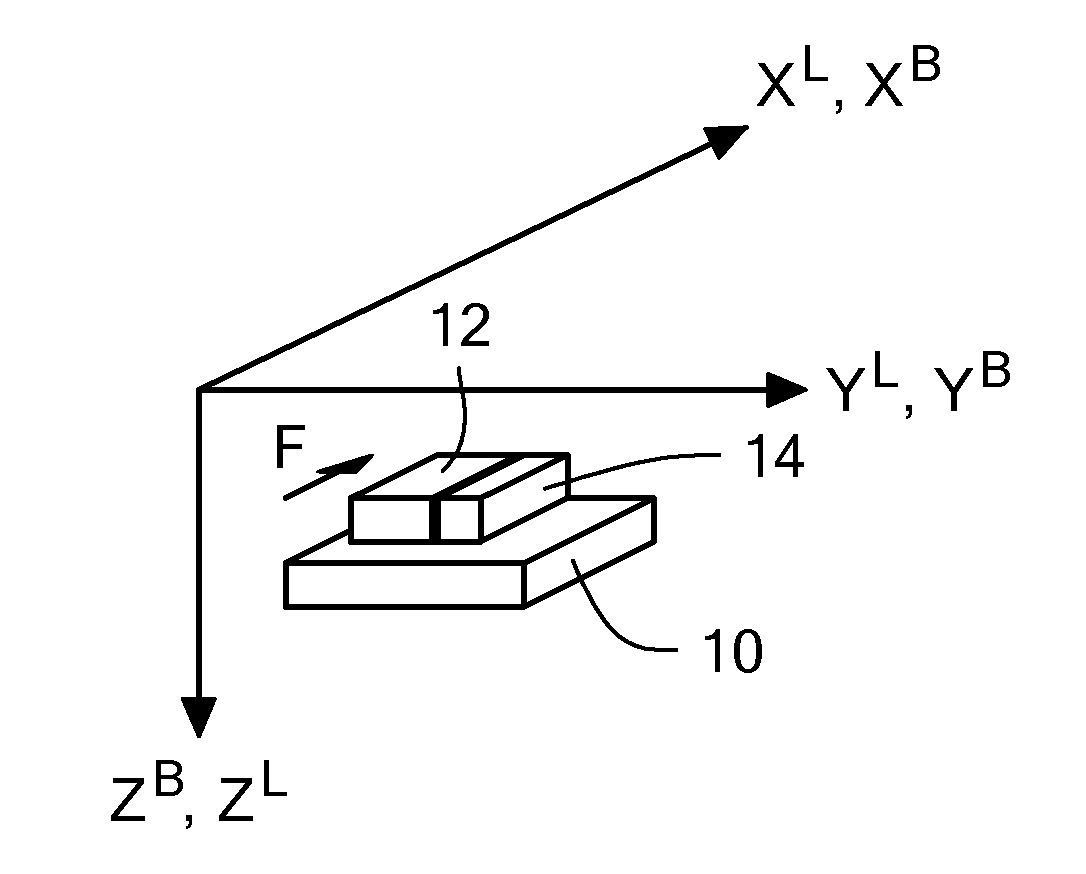
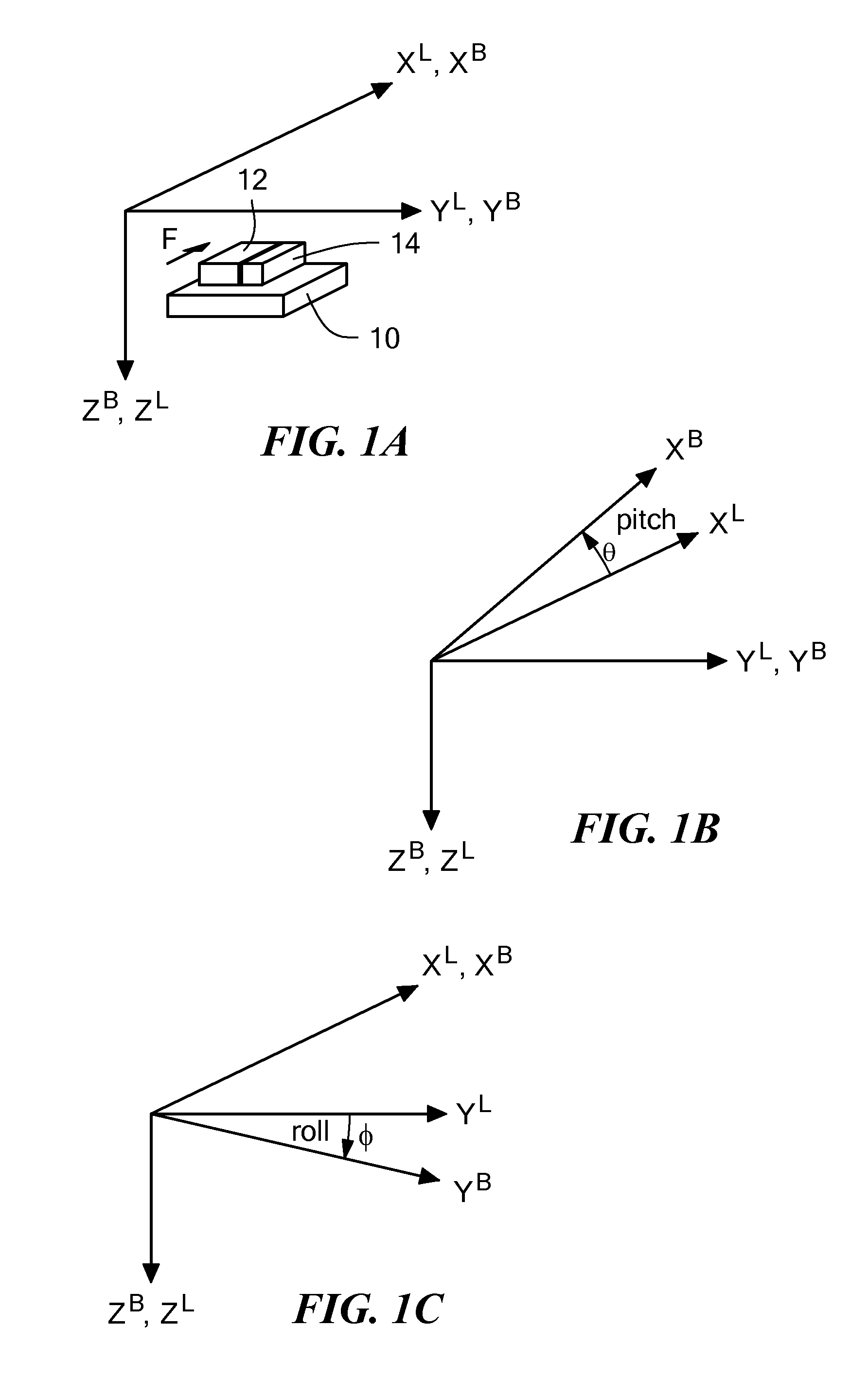
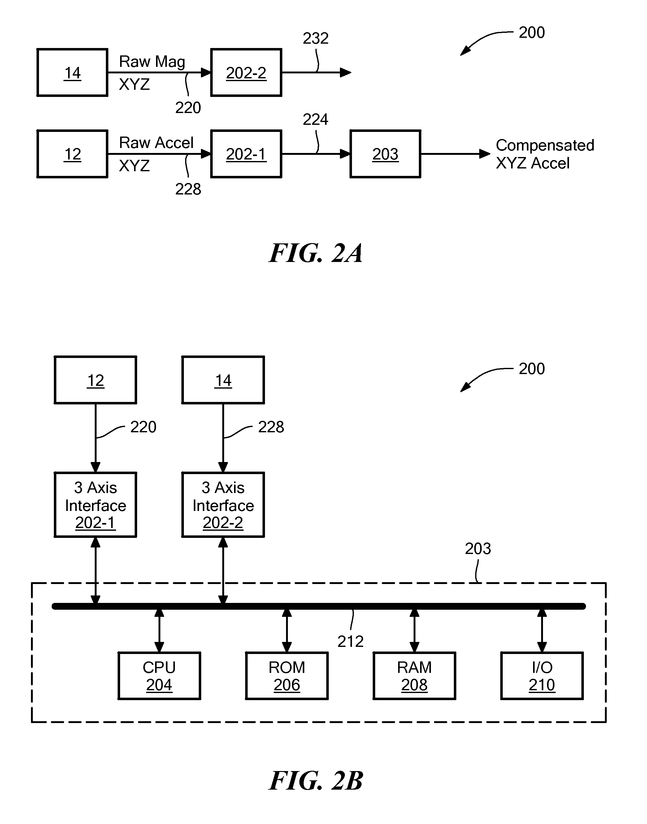
[0023]Embodiments of the present invention implement sensor data fusion, i.e., the combining of data available from accelerometer and magnetometer sensors in order to accurately determine heading and orientation of a device. The data fusion of a three-axis magnetometer and a three-axis accelerometer provides an attitude and heading, on-line calibrated magnetometer and accelerometer data, and an angular rates solution. As a result, a magnetometer sensor calibration to remove sensor error sources over time and temperature and to recover Earth's magnetic field measurements from hard and soft iron distortions is provided.

[0024]One embodiment of the present invention provides a method of providing a six-axis magnetic field / accele...


PUM


Abstract

Method and apparatus of integrating a three-axis magnetometer and a three-axis accelerometer to provide attitude and heading, calibrated magnetometer and accelerometer data, and angular rate, while removing sensor error sources over time and temperature and to compensate for hard and soft iron distortions of the Earth magnetic field. Filtered accelerometer data are corrected to account for various error sources. The magnetic heading is calculated from a horizontal magnetic field vector transformed from three dimensional Earth's magnetic field vector by using quasi-static roll and pitch angles from the filtered accelerometer data. A first Kalman filter estimates the state vector, based on the principle that the magnitude of local Earth's magnetic field vector is constant, to form hard and soft iron correction matrices. A second Kalman filter estimates a correction matrix of coupled remaining soft iron and the misalignment of the magnetometer and the accelerometer, as the dot product of local Earth's magnetic field vector and a corrected gravitational acceleration vector, at a quasi-static position, is constant. The three dimensional Earth's magnetic field vector is received by removing the hard and soft irons through the soft iron and hard iron correction matrixes.

Description

CROSS-REFERENCE TO RELATED APPLICATION[0001]Priority of U.S. Provisional Patent Application Ser. No. 61 / 678,638 for “Method for 6-Axis Magnetometer and Accelerometer Fusion with Intelligent Autonomous Calibration,” filed Aug. 2, 2012, is claimed.BACKGROUND OF THE INVENTION[0002]The availability of low cost and small microelectromechanical systems (MEMS) accelerometers has created a large variety of new commercial applications with their inclusion in smart phones and other handheld or mobile devices. For example, as compared with other types of MEMS accelerometer technologies, a thermal MEMS accelerometer, which is based on the principle of measuring internal changes of convection heat transfer due to the acceleration applied, has superior advantages for consumer applications, including a low cost fabrication process, high reliability and very good shock or impact resistance.[0003]Furthermore, advances in magnetometer technologies also make it possible (cost, size and power consumpti...

Claims


Application Information

Patent Timeline
Patent Type & Authority Applications(United States)
IPC IPC(8): G01C25/00G01P21/00G01R35/00
CPCG01C25/00G01P21/00G01R35/00G01C17/38G01P15/00G06F18/256
Inventor AN, DONGZHAO, YANGDING, HAIPENGLEE, JONG-KI
Owner MEMSIC
Why Eureka
Try Eureka