Integrated illumination and imaging system

a technology which is applied in the field of integrated illumination and imaging system, can solve the problems of increasing the size of the endoscope, and achieve the effects of less invasiveness, reduced complexity of the given endoscope, and reduced difficulty and cost of its manufactur

Inactive Publication Date: 2000-01-11
MICRO MEDICAL DEVICES
View PDF6 Cites 76 Cited by
  • Summary
  • Abstract
  • Description
  • Claims
  • Application Information

AI Technical Summary

Benefits of technology

functions as a self-filtering system due to the placement of the light emitting element with respect to the fibers which are transmitting illuminating light, thereby eliminating a sensation of glare when the image is viewed or recorded.
1. Removal of light guides to make the bundles smaller and therefore less invasive;
2. Reduction of the complexity of a given endoscope, which reduces the difficulty and the cost of its manufacture; and
Therefore, an endoscope operating by means of this proposed system can produce a higher resolution image than conventional endoscopes of equal cross-sectional area.

Problems solved by technology

Since many endoscopes require a separate light guide, this increases the size of the endoscope.

Method used


Image

  • Integrated illumination and imaging system
  • Integrated illumination and imaging system
  • Integrated illumination and imaging system

Examples


embodiment 1

Stationary Light Channeling

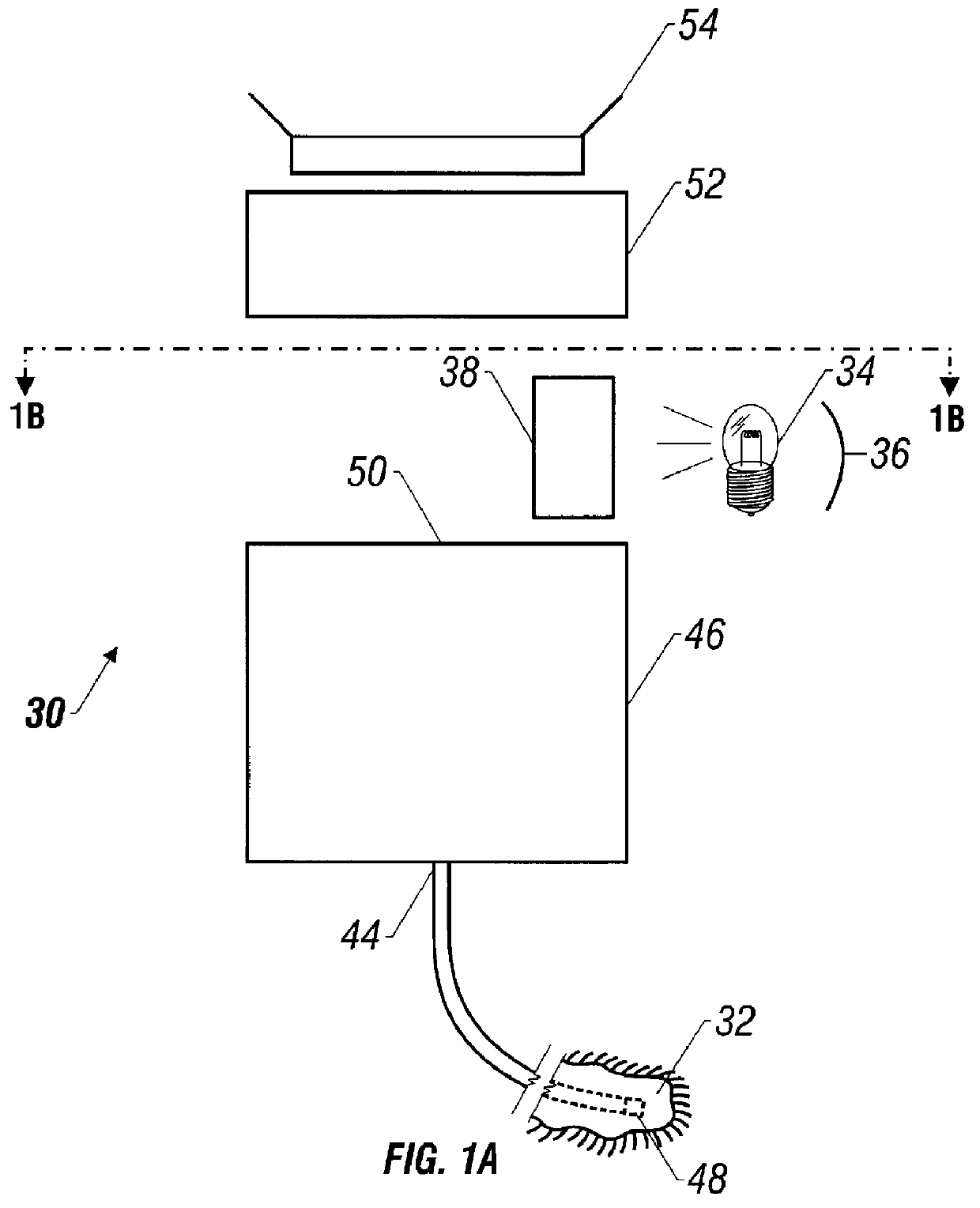
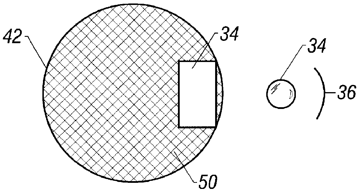
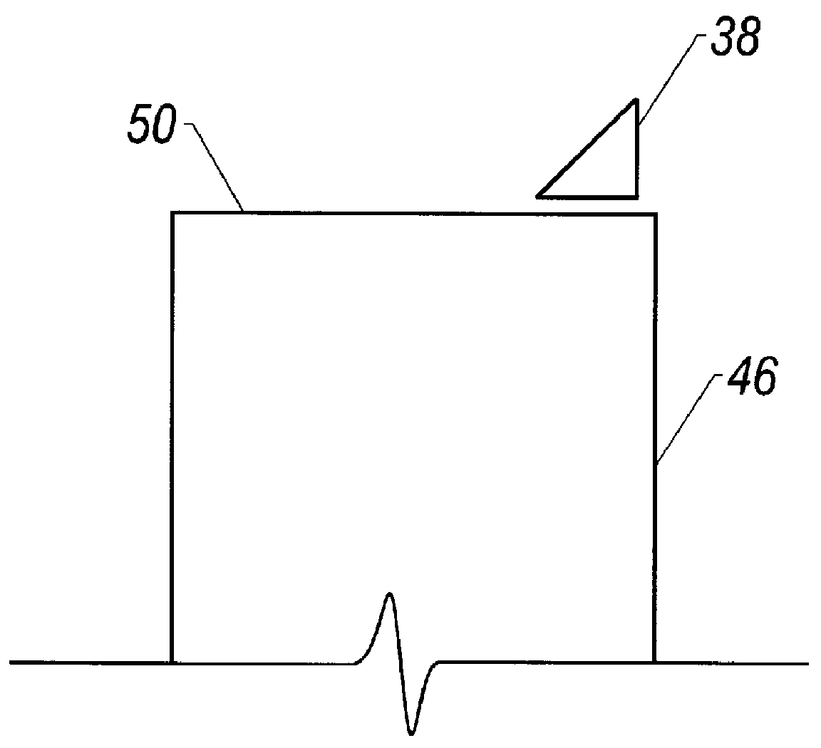
This first embodiment is shown in FIGS. 2A and 2B, and uses the operation of channeling above bundle.

Endoscope 30 includes light channeler 38 permanently mounted above the portion of the GRIN 46 or the image bundle. Light channeler is dedicated to illumination. Light from external source 34 is focused by focusing device 36 and aimed at light channeler 38, which then transmits this light onto the portion 56 of the bundle over which it is located. In this version of the device, section 56 of the image bundle located below the channeler 38 is permanently dedicated to illumination. The image receiving device records an image proximate distal end 48 of bundle 42 partially obscured by light channeler 38.

embodiment 2

The second embodiment uses stationary light channeling, and is shown in FIGS. 3A and 3B. This operates to carry out channeling with the bundle.

Endoscope 60 includes channeling device 61 integrated within the bundle. Channeler 61 is formed by notch 62 cut into outside wall 64 of bundle 66. Notch 62 has the proper geometry to receive light from direct light source 34 and divert the light toward the distal end of bundle 66. Light received from notch 62 travels through bundle 66. This system uses the exposed fibers 68 as being permanently dedicated to illumination. FIG. 3B shows that light channeling may be accomplished by one or more notches 62 placed in bundle wall 64, which expose one or more sets of fibers 68 to illuminating light.

embodiments 1 and 2

differ from current endoscope technology by eliminating the need for light guides for illumination. This is done by permanently dedicating a section of the image bundle fibers to serve the function of illuminating the sight of examination at the distal end of endoscope.

The remaining embodiments, unlike embodiments 1 and 2, use light channeling devices are in motion with respect to the fiber optic bundle they are illuminating, and the device used to record the image (the camera). The channelers at a given instant in time obscure the bundle from view as do those in embodiment 1, yet the portion they obscure is not the same over time. The motion of the channeler(s) is fast enough that the recorded image appears like an image seen through a propeller or ventilation fan in motion.

At any given moment, the portion of the image bundle exposed to the light channeling device may range from 100% to 0%. Equivalently, at any given moment, the portion of the image bundle exposed to the optical re...


PUM


Abstract

A miniaturized endoscope is formed by passing light in both directions down the endoscope.

Description

FIELD OF THE INVENTIONThe present application describes an integrated illumination and imaging system. In one form, these concepts are particularly adapted for use with an endoscope which has the capacity to illuminate a site of investigation and transmit an image of that site by an image carrying transmission medium.BACKGROUND OF THE INVENTIONMicro invasive surgery has a goal of minimizing the amount of damage caused during surgery. Some surgical procedures, for example, can be obviated by using an endoscope through a small incision. The size of the incision, therefore, depends on the size of the endoscope. One important feature of an endoscope, therefore, is its size. Since many endoscopes require a separate light guide, this increases the size of the endoscope.Current endoscopes often use some type of illumination bundles or light guides to couple light to a site of viewing. The site of viewing is then imaged by appropriate receiving of the coupled light that is reflected by the ...

Claims


Application Information

Patent Timeline
Patent Type & Authority Patents(United States)
IPC IPC(8): A61B1/07A61B1/06
CPCA61B1/07A61B1/0669
Inventor BONNE, ULRICH A.HOLROYD, JAMES A.J.WULFMAN, DAVID R.JEFFREY, DAVID H.ERDMAN, ARTHUR G.
Owner MICRO MEDICAL DEVICES
Why Eureka
Try Eureka