Method of continuous tone imaging to provide an imaged high loft mat product

Inactive Publication Date: 2000-01-11
3M INNOVATIVE PROPERTIES CO
View PDF9 Cites 27 Cited by
  • Summary
  • Abstract
  • Description
  • Claims
  • Application Information

AI Technical Summary

Benefits of technology

It is further understood that other machines that apply inks, dyes or pigments may be utilized in accordance with the principles discussed above. Specifically, the mat characteristics are not to be degraded. Moreover, a sufficiently clear continuous tone image is to be provided within the three dimensional structure by applying ink sufficiently within the three dimensional structure including its top surface. It is also noted that the above-described bonding material, e.g., plastisol for a vinyl mat, may be applied before the imaging process and again after, may only be applie

Problems solved by technology

These attempts were highly unsuccessful in that the dyes migrated substantially into the web material and diffused within its structure to the point where the image sharpness was not acceptable.
However, the problem with such an imaged mat was that the image was not nearly as durable as the structural durability of the mat and wore off much more quickly than the mat wore out.
Specifically, the void volume of the open spaces was significantly decreased, thus taking away from the mat's ability to hold dirt and water and rendered the mat significantly heavier.
The images obtainable are limited

Method used


Image

  • Method of continuous tone imaging to provide an imaged high loft mat product
  • Method of continuous tone imaging to provide an imaged high loft mat product
  • Method of continuous tone imaging to provide an imaged high loft mat product

Examples


example # 1

Example #1 The web used was prepared according to U.S. Pat. #4,351,683--Example #1 except the plastisol binder was:

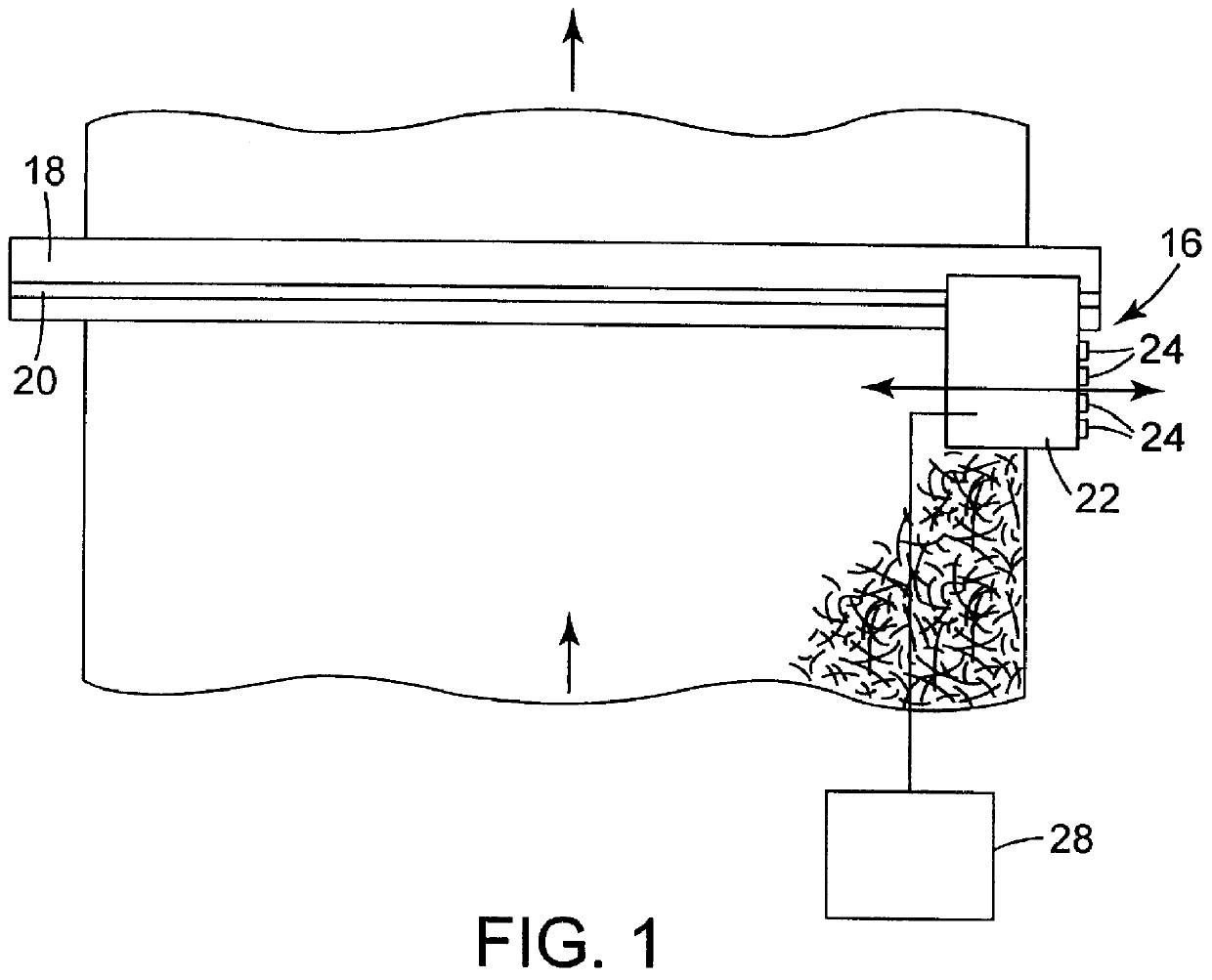
The resulting matting material was printed with a digitized image of a 3M.TM.Scotchgard.TM. fabric protector 10 oz. can using a Scitex "Outboard" Printing machine at 10 dpi resolution. It was necessary to modify the gap between the printing head and backup plate to allow the 0.4 inch (10.2 mm) thick mat to feed through the machine. The inks used were purchased from Imaje Ink Jet Printing Corporation, of Kennesaw, Ga.

The imaged mat was then roll coated again with the aforementioned plastisol binder and bonded in a forced air oven at 300.degree. F. (150.degree. C.) for 3 minutes to produce a durable imaged mat. By "durable imaged", it is meant that the mat life is approximately equal to that of the image life. By "Image Life", it is meant that point at which the image is degraded beyond easy recognition. Void volume and other mat characteristics remained substantially unc...

example # 2

Example #2 The web used was prepared according to Example #1 and then backed according to U.S. Pat. #3,837,988. The only change was the foam backing formulation:

The resulting web was then printed with a digitized pattern according to Example#1 and coated with plastisol to produce a durable imaged mat. Void volume and other mat characteristics remained substantially unchanged.

example # 3

Example #3 The web described in Example #1 was extruded according to U.S. Pat. #3,837,988 but not coated with a plastisol binder. The resulting unbonded web was then backed according to Example #2 and printed with a digitized image according to Example #1 of a 3M.TM. Scotchgard.TM. fabric protector 10 oz. can using a Scitex "Outboard" Printing machine at 10 dpi resolution. The resulting web was then coated with plastisol according to Example #1 to produce a durable imaged mat. Void volume and other mat characteristics remained substantially unchanged.


PUM

PropertyMeasurementUnit
Fractionaaaaaaaaaa
Fractionaaaaaaaaaa
Fractionaaaaaaaaaa

Abstract

A method for continuous tone imaging on a mat product having a web material with a three dimensional open structure provides a mat product with a sufficiently clear image. Moreover, it is a specific aspect of the present method to provide a clear image on such a three dimensional structure without negatively affecting the characteristics of the web material having the three dimensional structure. More specifically, the present invention is directed to a method for imaging a flexible high loft matting material which can be used in providing a floor covering mat product. The present invention is also directed to the imaged mat product produced in accordance with this method.

Description

The present invention relates to an imaging process for applying a color image to a high loft mat material. More specifically, the image is applied to the three dimensional structure of a high loft mat material in a way so as to provide a clear full color continuous tone image which does not degrade the functional attributes of the mat material.High loft composite materials have long been known which are suitable for use as matting material. Many types have been developed, and the present invention is particularly directed to those of the type having a three dimensional open structure for providing high loft.The present invention was particularly developed for its application to matting material comprising an open structure of interengaged continuous, coiled filaments of thermoplastic material. Such a structure provides a resilient, crush resistant and tough unitary open structure that is dimensionally stable. In some cases, the matting material is characterized further by having a ...

Claims


Application Information

Patent Timeline
IPC IPC(8): B41J2/01D06P5/30D06P5/00D06B11/00
CPCB41J2/01D06B11/0059D06P5/001D06P5/30Y10T428/23929Y10T428/23957Y10T428/23993Y10T428/23936B32B3/02
Inventor MARTIN, PHILIP G.OLSON, GARY L.RIDLEHOOVER, GERALD A.SCHICKLER, RANDALL R.
Owner 3M INNOVATIVE PROPERTIES CO
Why Eureka
Try Eureka