EAS system antenna configuration for providing improved interrogation field distribution

a technology of interrogation field and antenna configuration, which is applied in the direction of burglar alarm mechanical actuation, burglar alarm by hand-portable object removal, instruments, etc., can solve the problems of increasing the false alarm of either or both non-marker objects in the interrogation zone, unfavorable interrogation field distribution, and regulatory or other practical constraints on the peak signal level that can be generated

Inactive Publication Date: 2000-02-01
SENSORMATIC ELECTRONICS CORP
View PDF25 Cites 94 Cited by
  • Summary
  • Abstract
  • Description
  • Claims
  • Application Information

AI Technical Summary

Benefits of technology

It is accordingly an object of the invention to provide an antenna configuration for use in an electronic ar...

Problems solved by technology

One significant obstacle to achieving these objectives is the uneven interrogation field distribution commonly provided by antennas used for generating the interrogation signal.
As a result of the uneven field distribution, the interrogation field may be strong enough at some or most locations in the interrogation zone to provide for detection of a marker, while not being strong enough at other locations to provide for detection.
This problem is aggravated by the fact that the strength of the signal generated by the marker is dependent on the ...

Method used


Image

  • EAS system antenna configuration for providing improved interrogation field distribution
  • EAS system antenna configuration for providing improved interrogation field distribution
  • EAS system antenna configuration for providing improved interrogation field distribution

Examples


first embodiment

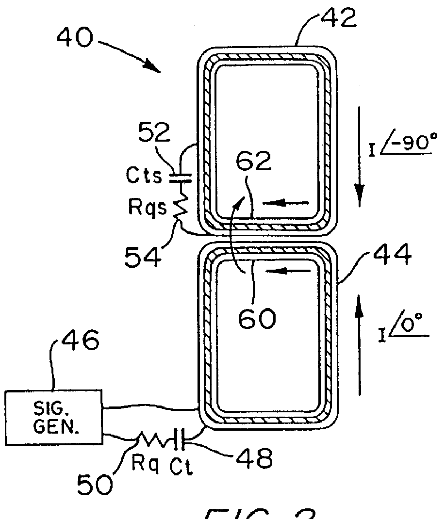
An antenna configuration for generating an interrogation field and provided in accordance with the invention will now be described with reference to FIG. 2. In FIG. 2 reference numeral 40 generally indicates the antenna configuration, which includes two co-planar antenna loops 42 and 44. The loops may, for example, both be rectangular and of like shape and size, and arranged, as shown in FIG. 2, with one loop stacked vertically above the other. Signal generating circuitry 46 is connected to the antenna loop 44 to directly generate an alternating current in the loop 44.

A capacitance 48 and resistance 50 are provided in series with the antenna loop 44 and a capacitance 52 and resistance 54 are provided in series with the antenna loop 42.

FIG. 3 is an equivalent circuit representation of the arrangement of FIG. 2. In addition to the elements described in connection with FIG. 2, FIG. 3 also shows a loop resistance 56 provided by loop 44 and a loop resistance 58 provided by loop 42.

As sho...

second embodiment

An antenna configuration 63 provided in accordance with the invention is illustrated in FIG. 4. The antenna configuration 63 includes an antenna housing 64, shown in phantom, within which are housed antenna loops 66, 68, and 70. A signal generating circuit 72 is connected to the antenna loop 66 to generate an alternating current in the loop 66. A signal generating circuit 74 is connected to the loop 68 to generate in the loop 68 an alternating current at the same frequency as the current in loop 66, but 90.degree. out of phase with the current in loop 66. Also, a signal generating circuit 76 is connected to the loop 70 to generate in the loop 70 an alternating current at the same frequency as, but 180.degree. out of phase with, the alternating current in loop 68.

The antenna loop 66 is substantially rectangular and planar, and the loops 68 and 70 are substantially co-planar with each other. The plane of the antenna loop 66 is substantially parallel to the common plane of loops 68 and...

third embodiment

An antenna configuration 63' according to the invention is illustrated in FIG. 6.

The antenna configuration 63' is the same as the configuration 63 of FIG. 4, except that the single loop 66 of FIG. 4 is replaced by side-by-side rectangular co-planar loops 66' and 78. The loop 66' is driven by the previously described signal generating circuit 72, and an additional signal generating circuit 80 is connected to loop 78 to generate an alternating current in loop 78 that is at the same frequency but 180.degree. out of phase with the current in loop 66'. The antenna configuration 63' of FIG. 6 provides a relatively even field distribution in the interrogation zone, like that provided by the antenna configuration of FIG. 4, while providing the additional feature of far-field cancellation by virtue of the two pairs of "bucking" loops 63' and 78, and 68 and 70.

As shown in FIG. 6, loop 68 includes a horizontal segment 82, a vertical segment 84 extending downwardly vertically from a right end o...


PUM


Abstract

In an electronic article surveillance system, quadrature transmitting and receiving antennas are used to improve field distribution. A transmitting antenna arrangement includes first and second adjacent co-planar antenna loops and excitation circuitry for generating respective alternating currents in the first and second loops such that the respective alternating currents are 90 DEG out of phase. In a receiving arrangement, respective signals received from two adjacent co-planar antenna loops are respectively phase-shifted by +45 DEG and -45 DEG , and the resulting phase-shifted signals are summed. A far-field cancelling transmitting antenna arrangement includes four loops operated at phases of 0 DEG , 90 DEG , 180 DEG and 270 DEG respectively. All four loops may be co-planar, with any bucking vertical segments being horizontally displaced from each other. Alternatively, the 0 DEG and 180 DEG loops may also be arranged in a common plane that is close to and parallel with another plane in which the 90 DEG and 270 DEG loops are arranged.

Description

This invention relates to antenna configurations, and more particularly to antennas for use with electronic article surveillance (EAS) systems.An electronic article surveillance system 20 is shown in schematic terms in FIG. 1. The system 20 is typically provided at the exit of a retail store to detect the presence of a marker 22 in an interrogation zone 24 defined between antenna pedestals 26 and 28. When the system 20 detects the marker 22, the system 20 actuates an alarm of some kind to indicate that an article (not shown) to which the marker 22 is secured is being removed from the store without authorization.Customarily, each of the antenna pedestals 26 and 28 is generally planar and includes one or more loop antennas. Signal generating circuitry 30 is connected to the antenna or antennas in pedestal 26 to drive the antennas in pedestal 26 to generate an interrogation signal in the interrogation zone. Also, receiver circuitry 32 is connected to the antenna or antennas in the pede...

Claims


Application Information

Patent Timeline
IPC IPC(8): G08B13/24H01Q7/04H01Q7/00G08B13/14
CPCG08B13/2471G08B13/2474G08B13/2477H01Q7/04
Inventor ALICOT, JORGE
Owner SENSORMATIC ELECTRONICS CORP
Why Eureka
Try Eureka