

Bridged coil catheter support structure
a support structure and coil technology, applied in the field of catheters, can solve the problems of catheters subjecting to high internal pressure, catheters with closed or geometric deformations, and undesirable closures or deformations
- Summary
- Abstract
- Description
- Claims
- Application Information
AI Technical Summary
Problems solved by technology
Method used
Image

Examples
Embodiment Construction
Referring now to the several drawing figures in which identical elements are numbered identically throughout, a description of a preferred embodiment of the present invention will now be provided.
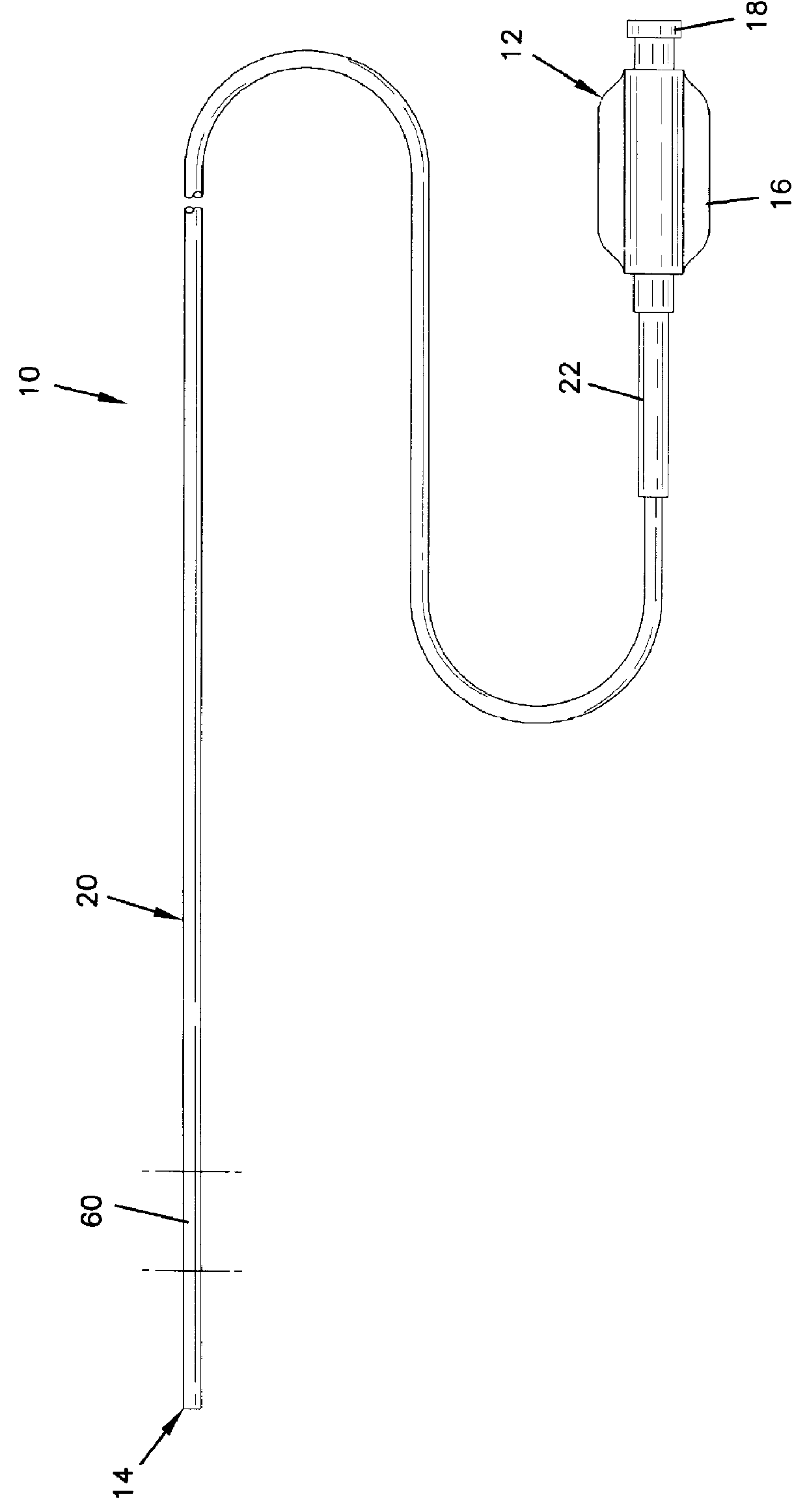
FIG. 1 illustrates a catheter 10. The catheter 10 extends from a proximal end 12 to a distal end 14. At the proximal end 12, a hub 16 is provided to be gripped by a physician as well as having an inlet 18 for injection of fluids into the catheter 10. A flexible hollow shaft 20 is connected to the hub 16. The shaft 20 is sized to be inserted into a patient's vasculature. The shaft 20 is commonly about 100 cm long. A strain relief jacket 22 connects the shaft 20 to the hub 16. The foregoing description forms no part of this invention and is given to facilitate an understanding of the present invention.
The catheter 10 includes a segment 60 having the novel construction of the present invention. (For purposes of the remainder of this description, the word "catheter" is generally used to refer t...
PUM
 Abstract
Description
Claims
Application Information