Incubation station for test sample cards

a test sample and incubation station technology, applied in the field of analytical instruments, can solve the problems of inability to achieve the above-described performance criteria for an incubation station the design is not optimal for use in a fully automated analytical instrument, and the change in light transmission characteristics

Inactive Publication Date: 2000-02-15
BIOMERIEUX INC
View PDF24 Cites 66 Cited by
  • Summary
  • Abstract
  • Description
  • Claims
  • Application Information

AI Technical Summary

Problems solved by technology

If the growth medium or reagent is specifically suited for or "matches up" with the particular microorganism in the fluid sample, the population of the microorganism increases substantially, or some other predetermined reaction, i.e., chemical reaction, takes place, which results in the well turning cloudy and thus having a change in light transmission characteristics.
As such, this design is not optimal for use in a fully automated analytical instrument in which the cards are prepared (i.e., loaded with the test sample) and introduced into and removed from the incubation station automatically.
Achieving the above-described performance criteria for an incubation station in a fully automated analytical instrument is a particularly difficult task.
First, the physical structures or framework that hold the cards in place in the incubation station can adversely effect the even flow and distribution of warm air introduced into the incubation station.
Second, this disruption in the distribution of warm air, caused by the carousel structures can lead to localized pools of warmer and cooler air or variances in air flow across the card, which can adversely affect the even or uniform incubation of the card and prolong the amount of time required to incubate the card sufficient to achieve a test result.
Third, the inventors have also discovered that the temperature and / or airflow at various locations in the incubation station are different relative to card position by an amount that is also sufficient to adversely affect the time needed to obtain test results.

Method used


Image

  • Incubation station for test sample cards
  • Incubation station for test sample cards
  • Incubation station for test sample cards

Examples


Embodiment Construction

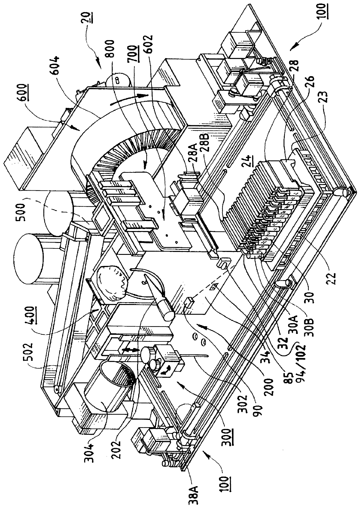
In FIG. 3, a card separation device comprising a wheel 94 attached to an arm that pivots about a pin 98 is shown. As the boat 22 and cassette 26 pass by the wheel 94, the wheel 94 rocks the cards 28 back within the slots of the cassette 26 to expose the upper surface of the card 28 and bar code affixed at this location to an optical reader 90 located forward of and above the card in the machine.

FIG. 23 is an isolated perspective view of an alternative and more preferred card separation device 102 that is also capable of card detection. FIG. 24 is a side elevational view of the card separation and detection device 102. FIG. 25 is a front elevation view of the device 102. FIG. 26 is an exploded perspective view of the device 102.

Referring to these figures, in conjunction with FIGS. 1, 2 and 3, the device 102 is mounted to a flange off of the center mount 34 in essentially the same manner and location as shown for the device 94 in FIG. 3, in a position "upstream" of the reading device ...


PUM

PropertyMeasurementUnit
temperatureaaaaaaaaaa
transmittanceaaaaaaaaaa

Abstract

Test sample cards containing biological samples are moved through an analytical instrument past a card detection device and detected by the device. The card detection device has an actuator that reciprocates relative to a housing between first and second positions. The actuator has a surface that comes into contact with the card as the card is moved past the device. The actuator carries an optical interrupt flag which is used in conjunction with an optical sensor placed in proximity to the actuator. When the card comes into contact with the actuator, the actuator is moved from the first position to the second, or retracted position. This action moves the flag relative to the optical sensor, triggering the optical sensor and a detection of the card. In one possible embodiment, multiple cards are placed in a cassette for movement around the instrument. The cassette has a number of slots for the cards, one card per slot. Each card has placed thereon indicia such as bar codes that are used for identification purposes by the instrument. The card detection device, in addition to performing the detection functions for each of the cards, also rocks the cards within the cassette slots so as to place the bar codes or other indicia into a better position for reading by a bar code reader or other appropriate reading device for the indicia.

Description

A. Field of the InventionThis invention relates generally to the field of analytical instruments for conducting biological sample testing. More particularly, the invention relates to a card detection device used in an analytical instrument to detect the presence of a card as the card is moved card through the instrument.B. Description of Related ArtA variety of test sample cards are described in the patent literature which have a well or reaction site for receiving a fluid sample containing a microbiological agent, such as a microorganism, and a reagent. Several representative patents include Meyer et al., U.S. Pat. No. 4,318,994, Charles et al., U.S. Pat. No. 4,116,775; Fadler et al., U.S. Pat. No. 4,038,151, O'Bear et al., U.S. Pat. No. 5,609,828 and Charles et al., U.S. Pat. No. 4,118,280. These patents describe a test sample card having a plurality of wells arranged in the test sample card body. The reagent is typically loaded in the wells of the card during the completion of ma...

Claims


Application Information

Patent Timeline
Patent Type & Authority Patents(United States)
IPC IPC(8): G01N35/00B01L3/00C12M1/38C12M1/18G01N1/00G01N1/38
CPCB01L3/50G01N35/00029Y10T436/115831G01N2035/00089G01N2035/00138G01N2035/00148G01N2035/00356G01N2035/0441G01N2035/0465Y10S435/809Y10T436/11Y10T436/112499Y10T436/113332Y10T436/114165G01N1/38G01N35/02
Inventor FREINER, BRENT D.ROBINSON, RONJUSTIN, MICHAEL JAMES
Owner BIOMERIEUX INC
Why Eureka
Try Eureka