Universal restraint clip fitting

a technology of universal restraints and clips, applied in the direction of snap fasteners, suspension devices, machine supports, etc., can solve the problems of compression brace buckling failure and shear forces at the fastener

Inactive Publication Date: 2000-02-22
DUGGAN WERNER INC
View PDF9 Cites 48 Cited by
  • Summary
  • Abstract
  • Description
  • Claims
  • Application Information

AI Technical Summary

Benefits of technology

It is a primary object of this invention to provide a universal restraint bracket having a structure and configuration that makes it suitable for simplified use in a cable tension system for dampening and sway reduction under seismic load conditions.
It is a further object of this invention to provide a restraint bracket or clip suitable for securement to a structural element such as a building wall or ceiling, to objects such as water pipes, electrical conduit, HVAC systems as well as their conventional supports and other apparatus used within the building to facilitate attachment of a cable system to dampen seismic shock induced apparatus sway.
It is an additional object of the invention to provide a restraint bracket for economical use in tensioned cable systems suitable for use with a single cable or a larger number of cables as the user may prefer.
It is yet another object of this invention to provide an easily manufactured universal restraint clip or bracket useable in the facile attachment of cables to a wide variety of objects, the clip being suitable for nesting to expand the cable attachment opportunities.

Problems solved by technology

It has been determined that using cables in tension to dampen loads and to reduce sway of the object being stabilized, whether that device is piping, HVAC duct, ceiling grids, electrical conduit or other building elements, is more effective than use of compression braces which introduce radius of gyration limitations that reduce damping of loads and often lead to compression brace buckling failure.
Moreover, attempts to secure a plurality of brackets with a single fastener to the stabilized object or to the support surface have, on occasion, created excessive bending moments and loads upon the single fastener, often producing shear forces at the fastener.

Method used


Image

  • Universal restraint clip fitting
  • Universal restraint clip fitting
  • Universal restraint clip fitting

Examples


Embodiment Construction

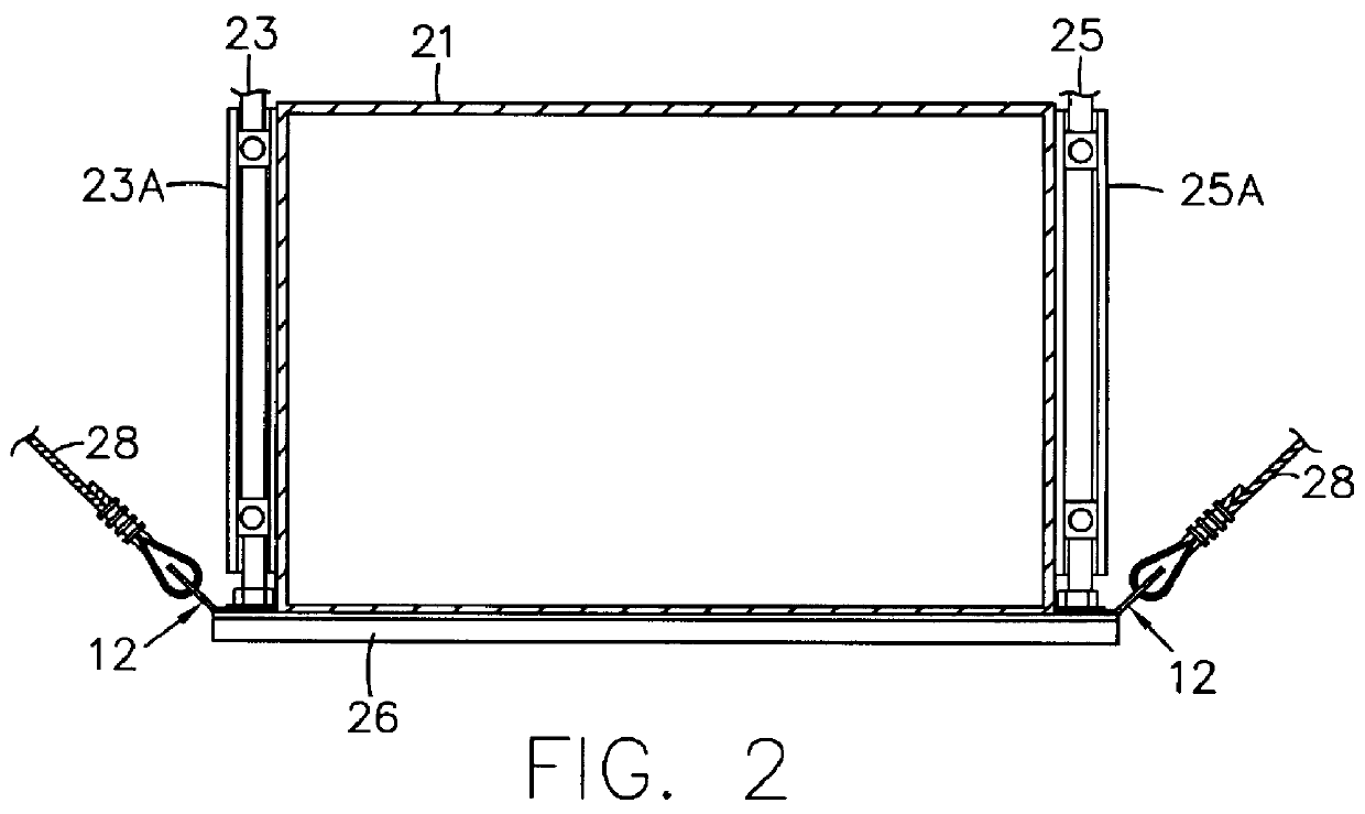
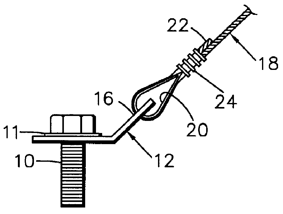
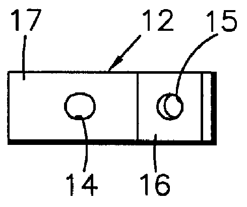
Before examining the details of the present invention, it is believed helpful to an understanding the present invention if the nature and status of typical prior art relating to shock bracing, particularly seismic shock bracing, are examined. Consideration of the prior art shown in the drawings is believed essential to an understanding of the problems solved by the present invention. Sway bracing systems to control object sway under, for example, seismic shock conditions have resulted in the preferred prior art use of tensioned cable systems to provide lateral and longitudinal or four-way tensioned cable sway control. Certain fundamental cable concepts have been drawn from the prior art, particularly the marine field, and a fundamental unit is found in FIGS. 1 and 1A. Threaded fastener 10 extends through a suitable washer 11 and bracket 12 having an aperture 14. Bracket 12 may be secured to an object whose sway is to be controlled or to the support structure (not shown) by fastener ...


PUM


Abstract

A universal one piece restraint bracket particularly suited for use with wire rope or cable for transverse, longitudinal and combined transverse and longitudinal seismic bracing systems for supporting an object. The bracket is generally L shaped to define a flattened apertured central portion with two wing portions generally at right angles to each other, apertured at their free ends and joined to the flattened central portion, each wing being elevated or upwardly bent away from the plane of the central portion. Aircraft type cables or wire rope connect the bracket to an adjacent support structure with the central portion of the bracket being secured to an object to be supported, whereby the bracing system acts in tension only so as to dampen earthquake loads and forces and thus is not subject to compression loads. A single bracket accommodates a wide variety of seismic bracing, and the bracket is configured for stacking with another bracket where necessary.

Description

This invention relates to bracing of piping, ductwork and other structural features of buildings and is more particularly directed to apparatus intended primarily for use with tensioned cable sway control systems through use of a single configuration bracket which can be effectively and economically used with a variety of objects to be braced in a variety of cable systems, particularly those providing lateral, longitudinal and four-way sway bracing systems. The invention finds significant usage in bracing structural elements to control seismic induced object sway in earthquake conditions.PRIOR ARTBecause of the random occurrence of seismic shock waves (earthquakes) and the resulting high damage to property and life, Congress enacted Public Law 95-124 known as the Earthquake Hazards Reduction Act, which act has been amended and made the subject of presidential executive orders. A federal government interagency committee on seismic security in construction has been establishing standa...

Claims


Application Information

Patent Timeline
Patent Type & Authority Patents(United States)
IPC IPC(8): E04H9/02
CPCE04H9/02Y10T24/4599Y10T24/3924Y10T24/3916Y10T24/4764F16L3/221
Inventor DUGGAN, DANIEL
Owner DUGGAN WERNER INC
Why Eureka
Try Eureka