Method for controlled transition between use of different injection waveform types in a hydraulically-actuated electronically-controlled fuel injection system

a technology control waveform, which is applied in the direction of electric control, liquid fuel feeders, machines/engines, etc., can solve the problems of mechanical limitations of electronically controlled fuel injection systems, increasing restrictions on engine exhaust emissions, and increasing the use of injectors

Inactive Publication Date: 2000-02-22
CATERPILLAR INC
View PDF27 Cites 29 Cited by
  • Summary
  • Abstract
  • Description
  • Claims
  • Application Information

AI Technical Summary

Benefits of technology

In another aspect of the present invention a method for controlling transfer from use of a first injection waveform type to use of a second injection waveform type in a hydraulically-actuated electronically-controlled fuel injection system of an engine includes sensing an engine speed and an engine load when the first injection waveform type is selected and storing the sensed engine speed and the sensed engine load. An actual engine speed is thereafter compared with the stored engine speed and an actual engine load is thereafter compared with the stored engine load. Transfer from use of the first injection waveform type to use of the second injection waveform type is prevented unless at least (i) a difference between the actual engine load and the stored engine load exceeds a predetermined load amount, or (ii) a difference between the actual engine speed and the stored engine speed exceeds a predetermined speed amount.

Problems solved by technology

Emission regulations pertaining to engine exhaust emissions are increasingly become more restrictive throughout the world, including, for example, restrictions on emission of particulates and NO.sub.x.
In the past hydraulically-actuated electronically-controlled fuel injection systems have included some mechanical limitations on the variety of achievable injection rate waveform types.
In some systems the injectors utilized have also been somewhat limited as to the control current waveform which could be utilized.
Resulting problems included injecting fuel too rapidly within a given injection event and allowing fuel to be injected beyond a desired stopping point.
Such problems can adversely affect emission outputs and fuel economy.

Method used


Image

  • Method for controlled transition between use of different injection waveform types in a hydraulically-actuated electronically-controlled fuel injection system
  • Method for controlled transition between use of different injection waveform types in a hydraulically-actuated electronically-controlled fuel injection system
  • Method for controlled transition between use of different injection waveform types in a hydraulically-actuated electronically-controlled fuel injection system

Examples


Embodiment Construction

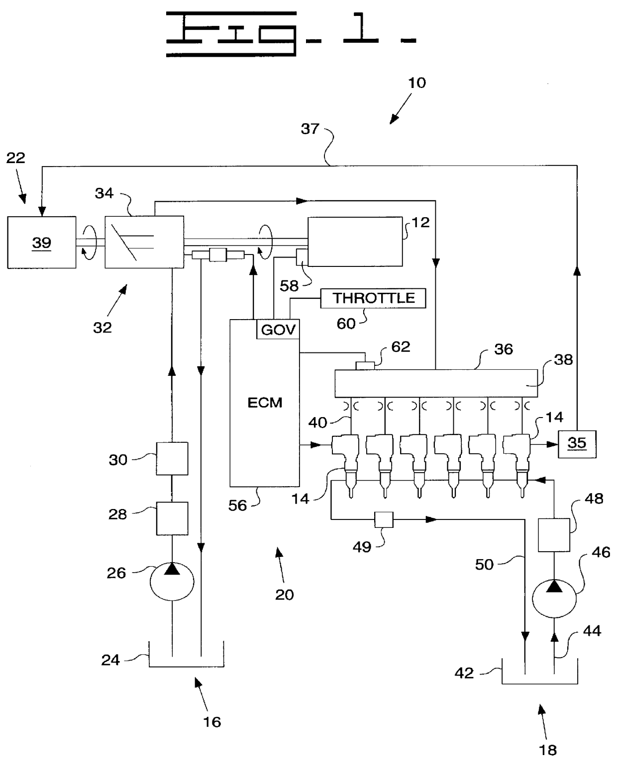
Referring to FIG. 1, there is shown a hydraulically-actuated electronically-controlled fuel injector system 10 (hereinafter referred to as HEUI-B fuel system). Typical of such systems are those shown and described in U.S. Pat. No. 5,463,996, U.S. Pat. No. 5,669,355, U.S. Pat. No. 5,673,669, U.S. Pat. No. 5,687,693, and U.S. Pat. No. 5,697,342. The exemplary HEUI-B fuel system is shown in FIG. 1 as adapted for a direct-injection diesel-cycle internal combustion engine 12.

HEUI-B fuel system 10 includes one or more hydraulically-actuated electronically-controlled injectors 14, such as unit fuel injectors, each adapted to be positioned in a respective cylinder head bore of engine 12. The system 10 further includes apparatus or means 16 for supplying hydraulic actuating fluid to each injector 14, apparatus or means 18 for supplying fuel to each injector, apparatus or means 20 for electronically controlling the manner in which fuel is injected by injectors 14, including timing, number of ...


PUM


Abstract

A method for controlling transfer from use of a first injection waveform type to use of a second injection waveform type in a hydraulically-actuated electronically-controlled fuel injection system of an engine includes sensing an engine speed and an engine load when the first injection waveform type is selected and storing the sensed engine speed and the sensed engine load. An actual engine speed is thereafter compared with the stored engine speed and an actual engine load is thereafter compared with the stored engine load. Transfer from use of the first injection waveform type to use of the second injection waveform type is prevented unless at least (i) a difference between the actual engine load and the stored engine load exceeds a predetermined load amount, or (ii) a difference between the actual engine speed and the stored engine speed exceeds a predetermined speed amount.

Description

This invention relates generally to hydraulically-actuated electronically-controlled fuel injection systems, and more particularly, to a method for controlling transition between use of two different injection waveform types within such a system.Emission regulations pertaining to engine exhaust emissions are increasingly become more restrictive throughout the world, including, for example, restrictions on emission of particulates and NO.sub.x. Tailoring the injection rate of fuel to a combustion chamber, as well as quantity and timing of such fuel injection, is one way in which to meet such emission regulations. At different engine operating conditions it may be necessary to utilize different injection rate waveforms in order to achieve optimum engine operation and emissions control.In the past hydraulically-actuated electronically-controlled fuel injection systems have included some mechanical limitations on the variety of achievable injection rate waveform types. In some systems t...

Claims


Application Information

Patent Timeline
Patent Type & Authority Patents(United States)
IPC IPC(8): F02D41/38F02D41/40
CPCF02D41/3827F02D41/402Y02T10/44Y02T10/40
Inventor BARNES, TRAVIS E.LUKICH, MICHAEL S.MCGEE, BRIAN G.PUCKETT, DANIEL R.TIMMONS, JOHN P.
Owner CATERPILLAR INC
Why Eureka
Try Eureka