
Method for performing powder material surface modification through plasma

A technology of plasma and powder materials, which is applied in metal material coating technology, gaseous chemical plating, coating, etc., can solve the problems of single material characteristics and cannot meet the application requirements of micron and nanometer powder materials, and achieve the purpose wide range of effects

Inactive Publication Date: 2016-02-10
ZHANGJIAGANG ULTRASONIC & ELECTRIC +2
View PDF2 Cites 22 Cited by
  • Summary
  • Abstract
  • Description
  • Claims
  • Application Information

AI Technical Summary

Problems solved by technology

[0002] With the continuous development of science and technology, the single characteristics of various materials can no longer meet the use requirements of products, and the tendency is to require materials to develop on the characteristics of composite materials, and to use a large number of cross-field technologies to improve material characteristics, especially in recent years. In the past few years, powder materials with micron and nanometer sizes have been developed and applied in large quantities. A common problem is that the material properties are single, and the modification is only some simple metal plating on the powder surface, and the process includes electroless plating or simple magnetron sputtering. Metal plating, part of the use of chemical vapor deposition CVD process, the above-mentioned powder modification process is mentioned in patents CN101082120B and CN103668112A, the main focus is on how to obtain uniform coating and equipment structure, fundamentally not on the powder surface and microstructure Modification and micro-infiltration of other characteristic materials, so the modification and application of powder materials are only limited to a surface physical processing, which still cannot meet the material application requirements of micron and nanometer powders

Method used


Image

  • Method for performing powder material surface modification through plasma
  • Method for performing powder material surface modification through plasma
  • Method for performing powder material surface modification through plasma

Examples


Embodiment 1

[0026] In this embodiment, the surface metallization modification of the prepared silicon carbide is as follows:

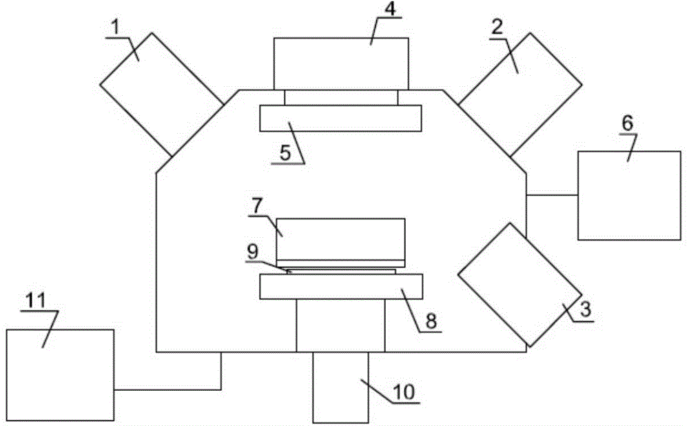
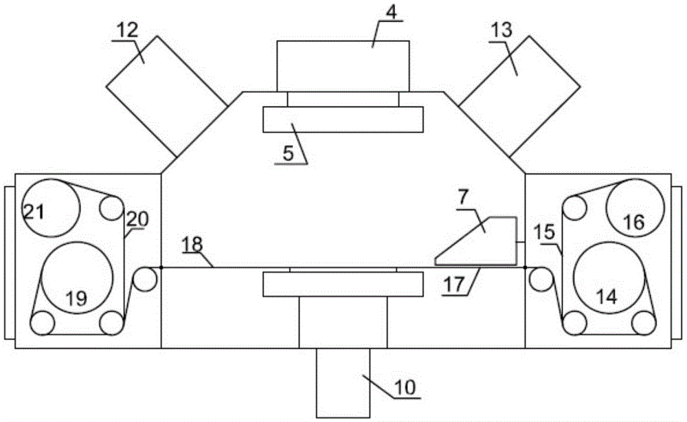
[0027] Select surface-cleaned silicon carbide powder with a particle size of about 5 microns and dry it and place it in the stocker 7 of the ultrasonic glass atomizer shown in Figure 1. The metal target 5 for modification is composed of nickel and titanium, and Use the assisted microetching ion source 1 and figure 2 The 17 powder electrostatic adsorption belt system is used to carry and transport the modified powder.

[0028] The silicon carbide surface metallization modification comprises the following steps:

[0029] 1. Uniform dispersion and film-making treatment of silicon carbide powder

[0030] Coat a layer of low-viscosity electrostatic adhesive coating on the aluminum film with a thickness of 20um and roll it up with anti-adhesive release paper. figure 2 For the coil 14 in the powder modification system, the layout of 16, 17, 19, and 21 in Figure 2 is...

Embodiment 2

[0035] This embodiment is to carry out metallization film formation to nano-graphene to improve its use environment process as follows:

[0036] Select the graphene nano-powder with surface cleaning treatment, its shape is 3 to 5 microns, the thickness of the sheet is about 1nm, dry it and place it in the ultrasonic atomizer stocker 7 in Figure 1, and modify the metal target 5 Composed of nickel and aluminum titanium, and using auxiliary microetching ion source 1 and shown figure 2 The 17 powder electrostatic adsorption belts carry and transport the modified powder.

[0037] Carrying out metallization film forming to nano-graphene comprises the following steps:

[0038] 1. Uniform dispersion of graphene powder to form a film

[0039] On the aluminum film with a thickness of 20um x660mm wide, first coat a layer of low-viscosity electrostatic adhesive coating and roll it up with anti-adhesive release paper. figure 2 Coil material 14 in, complete the layout of 16, 17, 19, 21...

Embodiment 3

[0045] This embodiment is to modify the honeycomb surface of single crystal or low-quality diamond as follows:

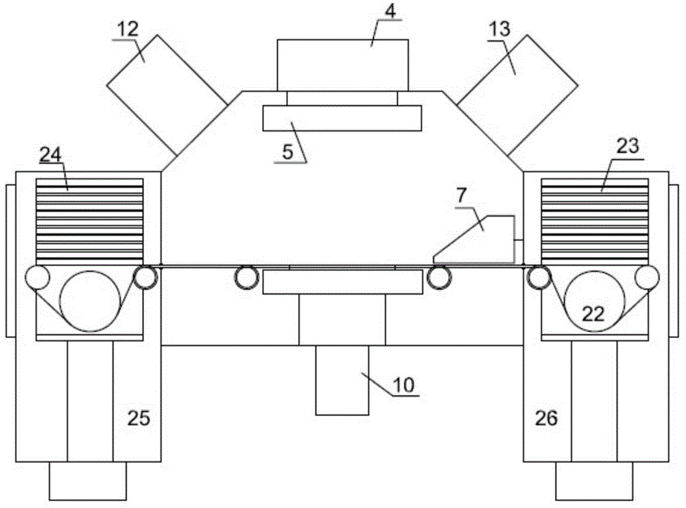
[0046] Select surface-cleaned diamond powder with a particle size between 2 and 10 microns. In this embodiment, select the diamond powder with a particle size of 3 microns and dry it and place it in the ultrasonic atomizer stocker 7 in Figure 1. The use of assisted microetching ion source 1 and image 3 The disk-type 23 powder electrostatic adsorption system in the machine is used to carry and transport the powder for modification.

[0047] The modification of described diamond surface honeycomb comprises the steps:

[0048] 1. Uniform dispersion of diamond powder

[0049] Evenly coat a layer of low-viscosity electrostatic adhesive coating on a 6-inch quartz glass wafer with a thickness of 5mm, and put it into the image 3 Complete the transmission layout of 22 in Figure 3 in the powder modification system on the wafer rack in 23, and add 100 grams of 3 micron di...


PUM

PropertyMeasurementUnit
particle diameteraaaaaaaaaa

Abstract

The invention discloses a method for performing powder material surface modification through plasma. According to powder material surface modification, under a vacuum environment condition, one or more plasma technologies are used for combination to deposit one or more different characteristic materials on the surfaces of powder materials in different types. Meanwhile, one ore more gases can be selected for combination for micro-etching on the surface of powder in different materials according to the plasma appearance. Powder manufactured and processed through the technology is a novel modified powder material with one or more functional characteristics. The modified powder is changed into a single-metal or multiple-metal combined surface from a non-metal surface, vice versa, the metal surface can be modified into a non-metal ceramic surface. Meanwhile, the smooth powder surface can be subjected to micro roughening.

Description

technical field [0001] The invention relates to a method for modifying the surface of a powder material with plasma, in particular, it relates to a powder material capable of modifying the surface of a powder material to make it a new material with different characteristics. At the same time, micro-etching and micro-infiltration can be carried out on the surface of the powder without changing the material of the original powder, so that the physical and chemical properties of the surface can be changed, so as to obtain powder materials with multiple composite functions and expand their technical applications. It belongs to the application field of composite material science and technology. Background technique [0002] With the continuous development of science and technology, the single characteristics of various materials can no longer meet the use requirements of products, and the tendency is to require materials to develop on the characteristics of composite materials, a...

Claims


Application Information

Patent Timeline
Patent Type & Authority Applications(China)
IPC IPC(8): B22F1/00C23C14/34C23C16/44C23F1/00C23F4/00
Inventor 兰育辉陈宏
Owner ZHANGJIAGANG ULTRASONIC & ELECTRIC
Learn More