Nut retaining plate

a technology of retaining plate and nut, which is applied in the direction of threaded fasteners, screws, washers, etc., can solve the problems of increased cost of cage and its attachment to the workpiece, difficulty or inability of the assembler to engage the nut on the side of the workpiece with a standard wrench or socket, and difficulty in using such a welded nu

Inactive Publication Date: 2000-02-22
DEERE & CO
View PDF9 Cites 54 Cited by
  • Summary
  • Abstract
  • Description
  • Claims
  • Application Information

AI Technical Summary

Problems solved by technology

Manufacturers use various methods for securing a plurality of members together in blind, semi-blind, or otherwise awkward assembly situations which do not permit a simple fastening with a nut, bolt and standard tools.
For example, where access to one side of a workpiece is restricted, it may be difficult or impossible for an assembler to engage a nut on that side of the workpiece with a standard wrench or socket while simultaneously engaging the head of a bolt on the other side.
However, making use of such a welded nut may prove difficult because the weldment makes no allowance for tolerances as the nut is immovable with respect to the workpiece.
The cage nut functions adequately, but the fabrication of the cage and its attachment to the workpiece represent increased cost.
However, these specialized tools must be used every time the bolt is ever removed and reinstalled.
Therefore, anyone wishing to remove the article from the workpiece must have access to the specialized tools, as the operation will likely be difficult or impossible to accomplish with standard tools.
In addition to drilling the three holes, it is then necessary to extend the rivets through the outer openings and upset the

Method used


Image

  • Nut retaining plate
  • Nut retaining plate

Examples


Embodiment Construction

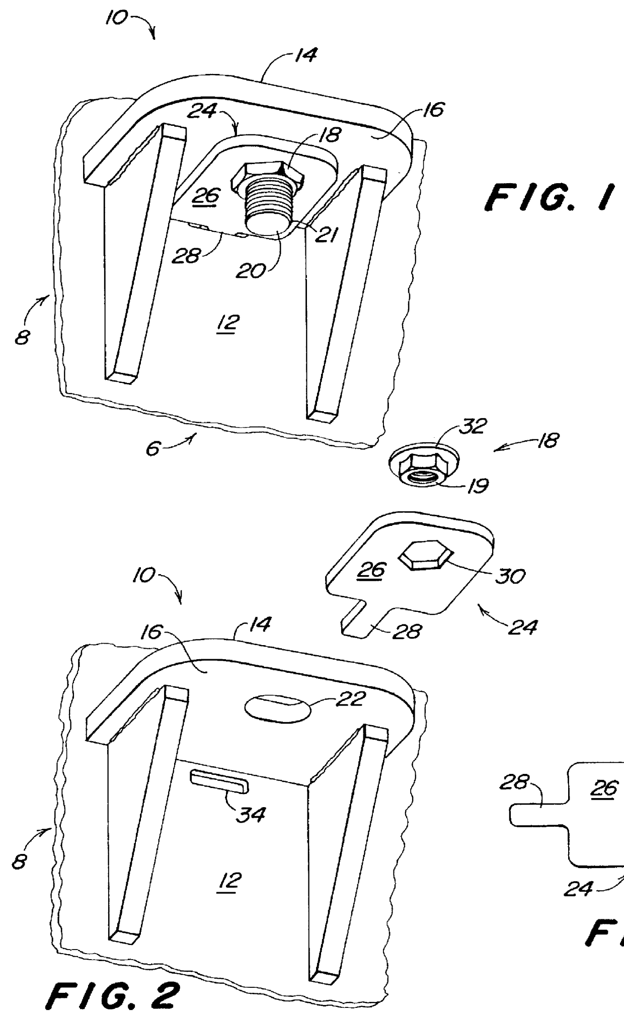
A fastening assembly 6 according to the present invention is shown in FIG. 1. A workpiece 8 comprises a mounting bracket 10 secured to a main frame 12. The mounting bracket 10 has upper and lower surfaces 14, 16, wherein an article such as an engine (not shown) may be secured to the main frame 12 by placing the article on the upper surface 14 of the mounting bracket 10 and securing the article with a nut 18 and a bolt 20 wherein a threaded shank 21 of the bolt 20 is directed downwardly through an opening 22 (FIG. 2) in the mounting bracket 10 and into engagement with internal threads 19 (FIG. 2) of the nut 18, drawing the nut 18 upward against the lower surface 16 of the mounting bracket 10 to secure the article to the workpiece 8.

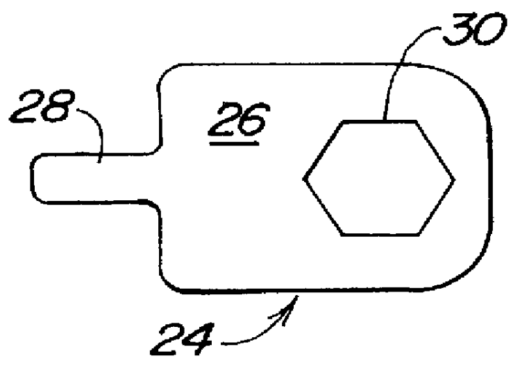
To accomplish the engagement of the bolt 20 with the nut 18 during assembly, a nut retainer 24 is used to hold the nut 18 in position below the lower surface 16 of the mounting bracket 10. The nut retainer 24 of the present invention as illustrated in FIGS...


PUM


Abstract

A fastener assembly is adapted for attaching an article to a workpiece having a slot. The fastener assembly includes a flanged nut which has internal threads and a non-circular cross-section, and a bolt having a threaded shank for engagement with the internal threads of the nut. The fastener assembly also includes a plate which comprises a main body and a tab portion extending from the main body. The plate has an opening complementary to the non-circular cross-section of the nut for receiving the nut therein and for securing the nut against rotation relative to the plate when the nut is placed in the opening. Alternatively, a nut is fixed to an underside of the plate against rotation and the opening in the plate is adapted for receiving the bolt therethrough. The tab portion of the plate extends into the slot in the workpiece for retaining the plate and nut and allowing limited float of the plate and nut with respect to the workpiece.

Description

1. Field of the InventionThe present invention relates to fasteners for assembly situations which otherwise do ot allow straightforward use of standard tools and assembly methods. More specifically, the present invention relates to apparatus for use in such a situation for holding a nut in position for assembly of a part to a workpiece where a degree of fastener float is desired.2. Description of Related ArtManufacturers use various methods for securing a plurality of members together in blind, semi-blind, or otherwise awkward assembly situations which do not permit a simple fastening with a nut, bolt and standard tools. For example, where access to one side of a workpiece is restricted, it may be difficult or impossible for an assembler to engage a nut on that side of the workpiece with a standard wrench or socket while simultaneously engaging the head of a bolt on the other side. Various methods have been employed to overcome this problem. For instance, a nut may be welded to one ...

Claims


Application Information

Patent Timeline
IPC IPC(8): F16B37/04F16B5/02
CPCF16B37/044F16B5/025F16B33/002Y10S411/971Y10S411/999
Inventor BEEMER, ANDREW PAULWINDSCHITL, PATRICK LEONARDCLINE, CHRIS ALLENRADKE, DANIEL DEAN
Owner DEERE & CO
Why Eureka
Try Eureka