I.S. machine

a technology of a machine and a frame is applied in the field of a machine and a frame is applied in the direction of glass blowing apparatus, baking, glass shaping apparatus, etc., which can solve the problem of high manufacturing cost of the method and achieve the effect of more economical

Inactive Publication Date: 2000-03-07
EMHART GLASS SA
View PDF7 Cites 4 Cited by
  • Summary
  • Abstract
  • Description
  • Claims
  • Application Information

AI Technical Summary

Benefits of technology

It is accordingly an object of this invention to provide a more economical construction of supporting the flexible suspension trough assembly.

Problems solved by technology

For new machines, this method is expensive to manufacture.

Method used


Image

  • I.S. machine
  • I.S. machine
  • I.S. machine

Examples


Embodiment Construction

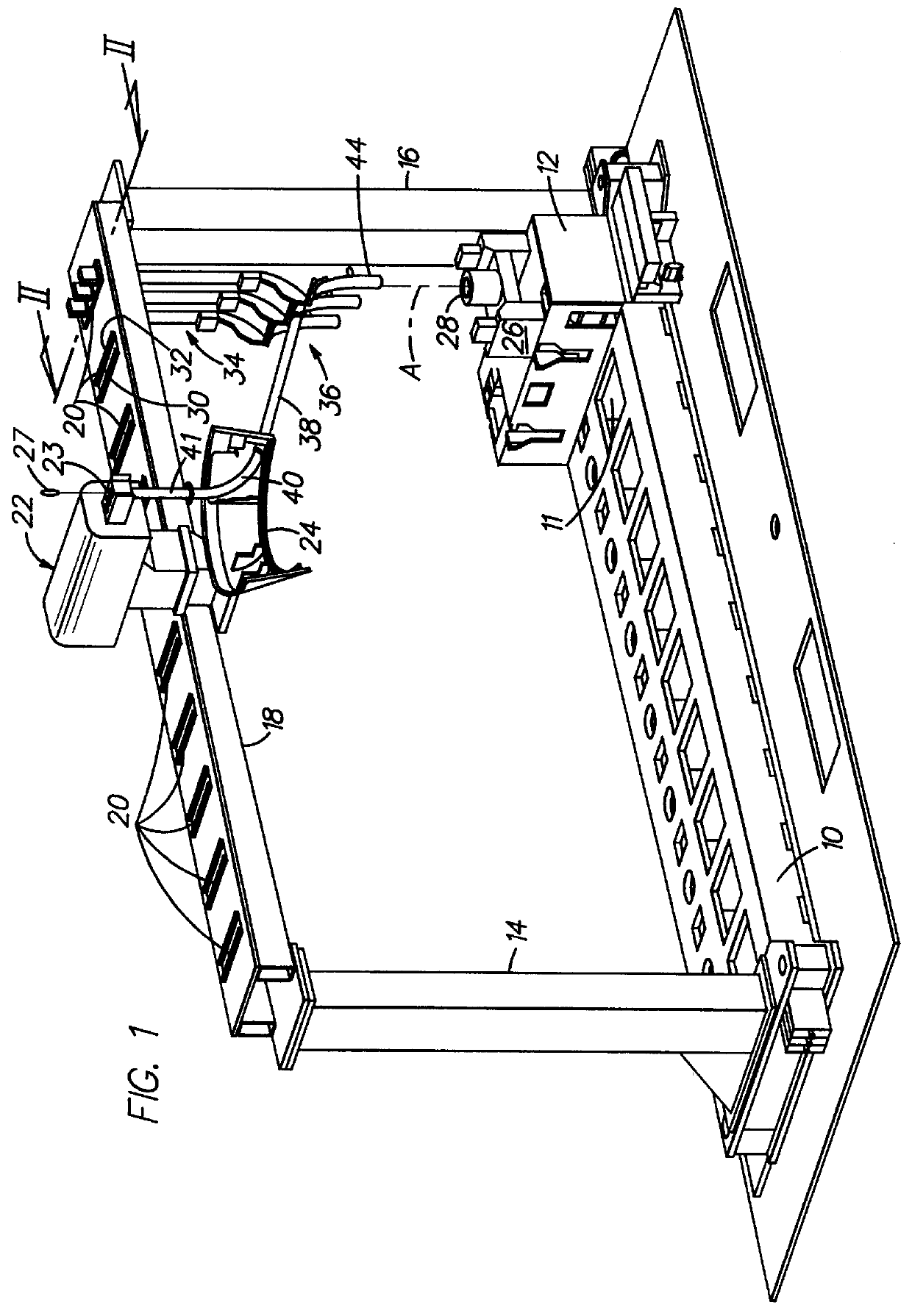
FIG. 1 discloses a machine bed 10 for an I.S. machine (here a ten section machine) which has a corresponding number of access openings 11 in its top surface. Fixed to its top surface, over these openings are a corresponding number of individual section frames 12. A first vertical upright 14 is fixed to the top surface of the machine bed at one end and a second vertical upright 16 is fixed to the top surface of the machine bed at the other end locating the individual section frames therebetween. Mounted across the top surface of the vertical uprights 14, 16 is a horizontal beam 18 which has a corresponding number of vertical openings 20. Also mounted to the horizontal beam are a gob distributor 22 which has a number of openings 23 corresponding to the number of gobs to be processed in each section (here the machine is a triple gob machine) and an upper trough support 24.

Each individual section 12 has a parison or blank mold supporting mechanism 26 having a parison mold 28 for each go...


PUM

PropertyMeasurementUnit
timeaaaaaaaaaa
flexibleaaaaaaaaaa
movementaaaaaaaaaa

Abstract

An I.S. glass forming machine is disclosed which has a plurality of individual sections each having a parison mold including a cavity having a first vertical axis. There is a trough assembly for each of the mold cavities which includes a deflector defining a second vertical axis. A horizontal beam supported by vertical uprights extends over the individual sections. The horizontal beam has a plurality of vertical openings corresponding to the number of individual sections of the machine which are in substantial alignment with the vertical axis of corresponding parison mold cavities. A corresponding plurality of hangers each defining a third vertical axis. The hangers are secured within the vertical openings with the third vertical axis coincident with the first vertical axis of a corresponding parison mold cavity and the trough assemblies are supported on a corresponding hanger with the third vertical axis of the hanger coincident with the second vertical axis of the supported deflector.

Description

The present invention relates to machinery for manufacturing glass containers, such as an I.S. (individual section) machine, and specifically to the overhead structure which supports the trough assembly portion of the delivery equipment that is used for delivering gobs of glass to the parison molds of each section.An I.S. machine has a number of identical sections, each of which has a blank station at which a number of gobs of molten glass (one, two, three four, . . . ) are formed into parisons and a blow station at which the parisons are blown into bottles. Each gob of molten glass is received by an individual mold at the blank station and a set of delivery equipment consisting of a scoop, trough, and deflector is associated with each mold for loading a molten gob, from the feeder into the blank or parison mold. The ideal design is to have this equipment form a straight line in the vertical plane from the centerline of the feeder orifice to the centerline of the parison mold cavity...

Claims


Application Information

Patent Timeline
Patent Type & Authority Patents(United States)
IPC IPC(8): C03B7/00C03B7/16C03B7/08C03B9/13C03B9/14
CPCC03B7/16
Inventor KAMMONEN, JARMO
Owner EMHART GLASS SA
Why Eureka
Try Eureka