Method and apparatus for compensating for thermal drift in a logic circuit

a logic circuit and output signal technology, applied in pulse automatic control, pulse manipulation, pulse technique, etc., can solve the problems of difficult and expensive systems to implement, circuitry required to provide an adjustable analog power supply signal to the integrated circuit is difficult and expensive to implement, and the delay between input and output signals is often somewhat dependen

Inactive Publication Date: 2000-03-07
CREDENCE SYSTEMS
View PDF5 Cites 28 Cited by
  • Summary
  • Abstract
  • Description
  • Claims
  • Application Information

AI Technical Summary

Benefits of technology

to provide a purely digital circuit which compensates for thermal drift of an output signal produced by a logic circuit.

Problems solved by technology

However the delay between input and output signals will often be somewhat dependent on the temperature of the integrated circuit implementing the logic circuit because the switching speed of gates forming the logic circuit is temperature dependent, particularly for CMOS integrated circuits.
Such systems are expensive and difficult to implement.
This system controls thermal drift well but the circuitry required to provide an adjustable analog power supply signal to the integrated circuit is difficult and expensive to implement.

Method used


Image

  • Method and apparatus for compensating for thermal drift in a logic circuit

Examples


Embodiment Construction

)

In many applications it is desirable that an output pulse produced by a logic circuit lag an input data or clock signal pulse by a fixed amount of time that is not dependent on the temperature of the logic circuit. However the delay between the input signal and the output signal is often temperature dependent, particularly in CMOS circuits. Such a logic circuit is said to be subject to "thermal drift" because the timing of its output signal drifts with respect to the input signal when the logic circuit temperature changes. The present invention compensates for such thermal drift.

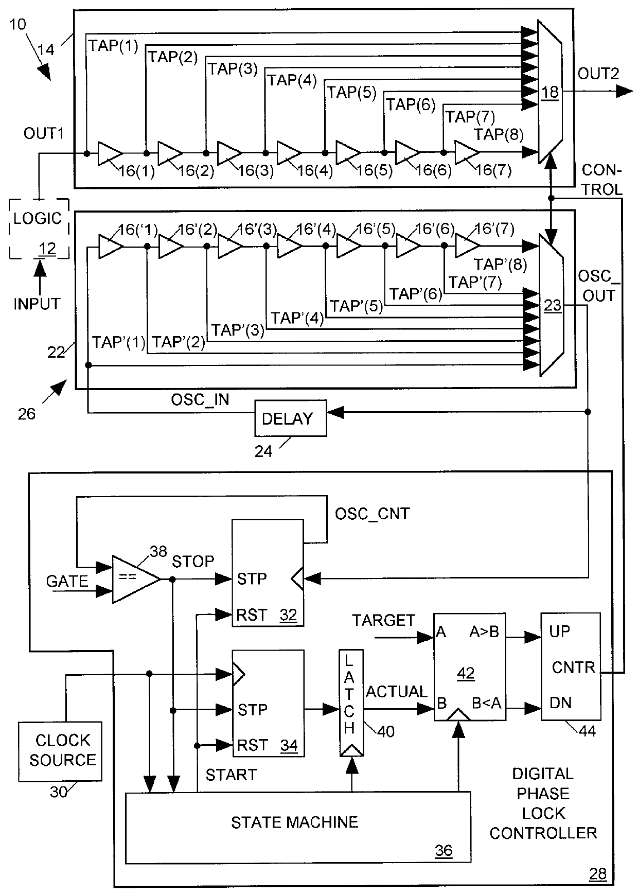
FIG. 1 illustrates in block diagram form a thermal compensation circuit 10, in accordance with the present invention, suitable for use in connection with a logic circuit 12 that is subject to thermal drift. Logic circuit 12 produces an output signal OUT1 in delayed response to an input signal INPUT with a delay that is temperature dependent. The INPUT signal may be a data signal or may be a periodic or an a...


PUM


Abstract

A system for compensating for thermal drift of an output signal (OUT1) produced by a logic circuit in response to an input CLOCK signal after a temperature dependent delay includes a variable delay circuit, an oscillator and a digital phase lock controller. The delay circuit delays the OUT1signal to produce a compensated output signal (OUT2) with a variable delay controlled by input CONTROL data. The oscillator generates an output signal (OSC-OUT) having a period also controlled by the input CONTROL data which is substantially proportional to the sum of the temperature dependent delay of the logic circuit and the delay of the variable delay circuit. The digital phase lock controller continually monitors the period of the OSC-OUT signal and adjusts the CONTROL data so that the period of the OSC-OUT signal remains substantially constant. This ensures that the delay between the CLOCK signal and OUT2 remains constant despite temperature dependent variations in the delay of the logic circuit.

Description

1. Field of the InventionThe present invention relates in general to a system for compensating for thermal drift of a logic circuit output signal.2. Description of Related ArtA typical digital logic circuit produces an output signal in delayed response to an input data or clock signal. It is often desirable that the logic circuit provide a fixed delay between the input signal and the output signal. However the delay between input and output signals will often be somewhat dependent on the temperature of the integrated circuit implementing the logic circuit because the switching speed of gates forming the logic circuit is temperature dependent, particularly for CMOS integrated circuits. This temperature dependency of the timing of the output signal with respect to the clock signal is known as "thermal drift".Some prior art thermal drift compensation systems attempt to control thermal drift by maintaining an integrated circuit at a constant temperature. Such systems include a heater fo...

Claims


Application Information

Patent Timeline
Patent Type & Authority Patents(United States)
IPC IPC(8): H03K5/13H03L7/099H03L7/08H03L7/16H03L7/181H03H11/26
CPCH03K5/13H03K5/131H03L7/0805H03L7/0997H03L7/181
Inventor VANDERSCHOOT, HENS CHRISTOPHERWASSON, TIMOTHY M.
Owner CREDENCE SYSTEMS
Why Eureka
Try Eureka