System and method for separating air flows in a cooling system

a cooling system and air flow technology, applied in the field of cooling systems, can solve the problems of total system shutdown, high internal temperature, and high temperature control, and achieve the effect of greater and greater efficiency

Inactive Publication Date: 2000-03-07
VERTIV CORP
View PDF6 Cites 307 Cited by
  • Summary
  • Abstract
  • Description
  • Claims
  • Application Information

AI Technical Summary

Benefits of technology

The growth of the computer industry and telephony over the past few decades has been phenomenal. The integration of these technologies, for example, in telecommunications switchi

Problems solved by technology

One problem inherent with all electronic equipment, telecommunications or otherwise, is temperature control.
As is readily apparent, if telecommunications switchi

Method used


Image

  • System and method for separating air flows in a cooling system
  • System and method for separating air flows in a cooling system
  • System and method for separating air flows in a cooling system

Examples


Embodiment Construction

The present invention will now be described more fully hereinafter with reference to the accompanying drawings, in which preferred embodiments of the invention are shown. This invention may, however, be embodied in many different forms and should not be construed as limited to the embodiments set forth herein; rather, these embodiments are provided so that this disclosure will be thorough and complete, and will fully convey the scope of the invention to those skilled in the art.

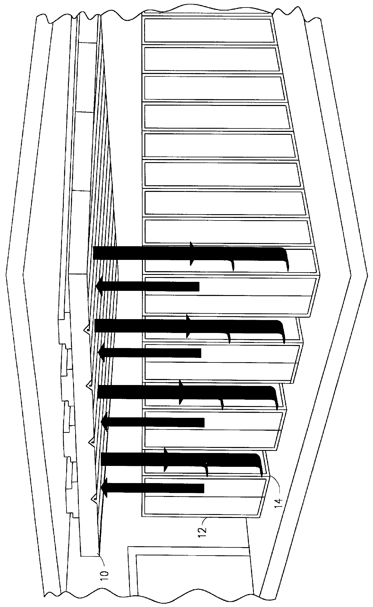
With reference now to FIG. 1, there is illustrated an equipment room with an overhead climate system 10 such as employed by Assignee and generally described in the aforementioned Swedish Patent Specification No. 8404878-4. As shown in FIG. 1, a number of rows of equipment 12 such as stored in cabinets are separated from each other by respective aisles, generally designated by the reference numeral 14, whereby a technician may access the equipment components. The aisles 14 also serve as convection pathways whe...


PUM


Abstract

A cooling system and method employing separation chutes and baffles is disclosed. The separation chutes separate the cooled air descending from a heat exchanger positioned above heat-generating equipment in an equipment room from heated air ascending from the heat-generating equipment. Separation of the airflows reduces turbulence and increases cooling efficiencies. The separation chutes are made of a variety of materials, both rigid and flexible, for a variety of applications.

Description

1. Technical Field of the InventionThe present invention relates to cooling systems for cooling electronic equipment, particularly to cooling systems employing suspended climate control systems using natural convection.2. Background and Objects of the InventionThe growth of the computer industry and telephony over the past few decades has been phenomenal. The integration of these technologies, for example, in telecommunications switching systems, has lead to greater and greater efficiencies as larger numbers of communications are handled by fewer components, which are typically housed in a central control room.One problem inherent with all electronic equipment, telecommunications or otherwise, is temperature control. As is readily apparent, if telecommunications switching equipment or other electronic components are not effectively cooled, high internal temperatures are quickly reached with total system shutdown soon following. Conventional approaches to cooling the aforementioned c...

Claims


Application Information

Patent Timeline
IPC IPC(8): H05K7/20
CPCH05K7/20745
Inventor ST.ANG.HL, LENNARTWALLACE, JR., JOHN FRANCISPARRAZ, JOHN CARLENASCLARK, MONTFORD HENRYWINN, DAVID
Owner VERTIV CORP
Why Eureka
Try Eureka