Reconfigurable system and method for cooling heat generating objects

a technology of cooling electronic equipment and reconfigurable systems, which is applied in the direction of domestic cooling equipment, lighting and heating equipment, electrical equipment casings/cabinets/drawers, etc., can solve the problems of difficult to modify the cooling system accordingly, the cooling characteristics of existing cooling systems are often a costly adventure, and the system rigidity is difficult to achieve. achieve the effect of greater and greater efficiencies

Inactive Publication Date: 2004-03-16
VERTIV CORP
View PDF11 Cites 16 Cited by
  • Summary
  • Abstract
  • Description
  • Claims
  • Application Information

AI Technical Summary

Benefits of technology

The growth of the computer industry and telephony over the past few decades has been phenomenal. The integration of these technologies, for example, in telecommunications switching systems, has lead to greater and greater efficiencies as larger numbers of communications are handled by fewer components, which are typically housed in a central control room.

Problems solved by technology

One problem inherent with many existing cooling systems for electronic equipment is rigidity.
In the event the temperature characteristics within the temperature-cooled room changes, such as by the equipment being moved within the room or by additional equipment being added therein, it is very difficult to modify the cooling system accordingly.
Consequently, altering the cooling characteristics of existing cooling systems frequently proves a costly adventure.
Floor-based cooling systems present additional difficulties other than rigidity in its cooling characteristics.
Such systems require the equipment cabling to be plenum rated, thereby increasing system cost.
Floor-based cooling systems also possess the tendency to distribute noise and vibrations, which may effect the operation of the equipment to be cooled.
In addition, floor-based and other existing cooling systems have a rather limited cooling capability.
Cooling systems having such heat densities, however, may not effectively cool today's equipment, such as state-of-the-art computational equipment.
As is readily apparent, if equipment is not effectively cooled, the internal temperature of the electronic components in the equipment substantially increases, thereby leading to significantly reduced system performance and, in some cases, total system failure.
If a cooling system inefficiently cools the equipment, either the equipment may fail due to increased operating temperature or the costs for cooling the equipment may be unnecessarily high.

Method used


Image

  • Reconfigurable system and method for cooling heat generating objects
  • Reconfigurable system and method for cooling heat generating objects
  • Reconfigurable system and method for cooling heat generating objects

Examples


first embodiment

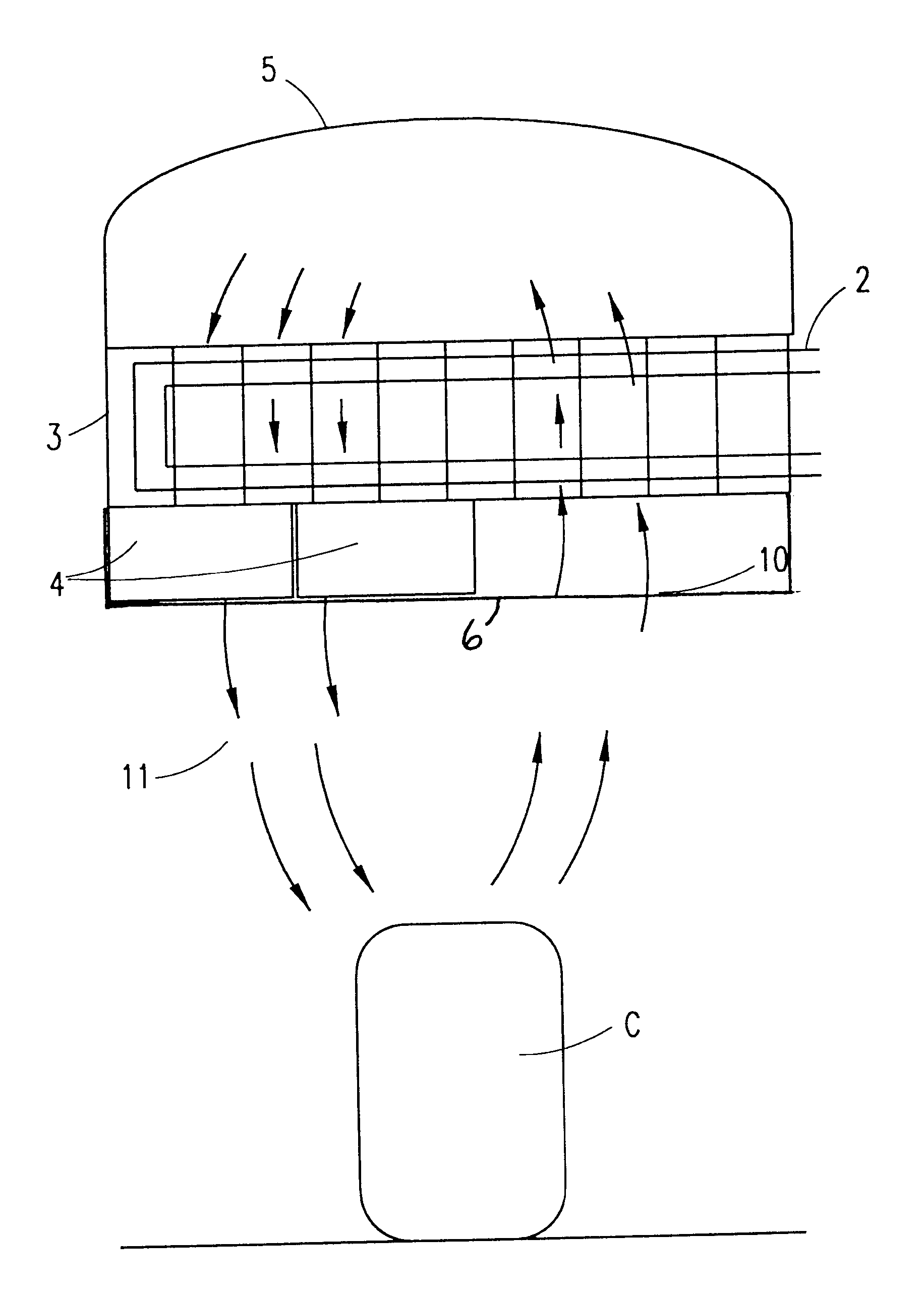
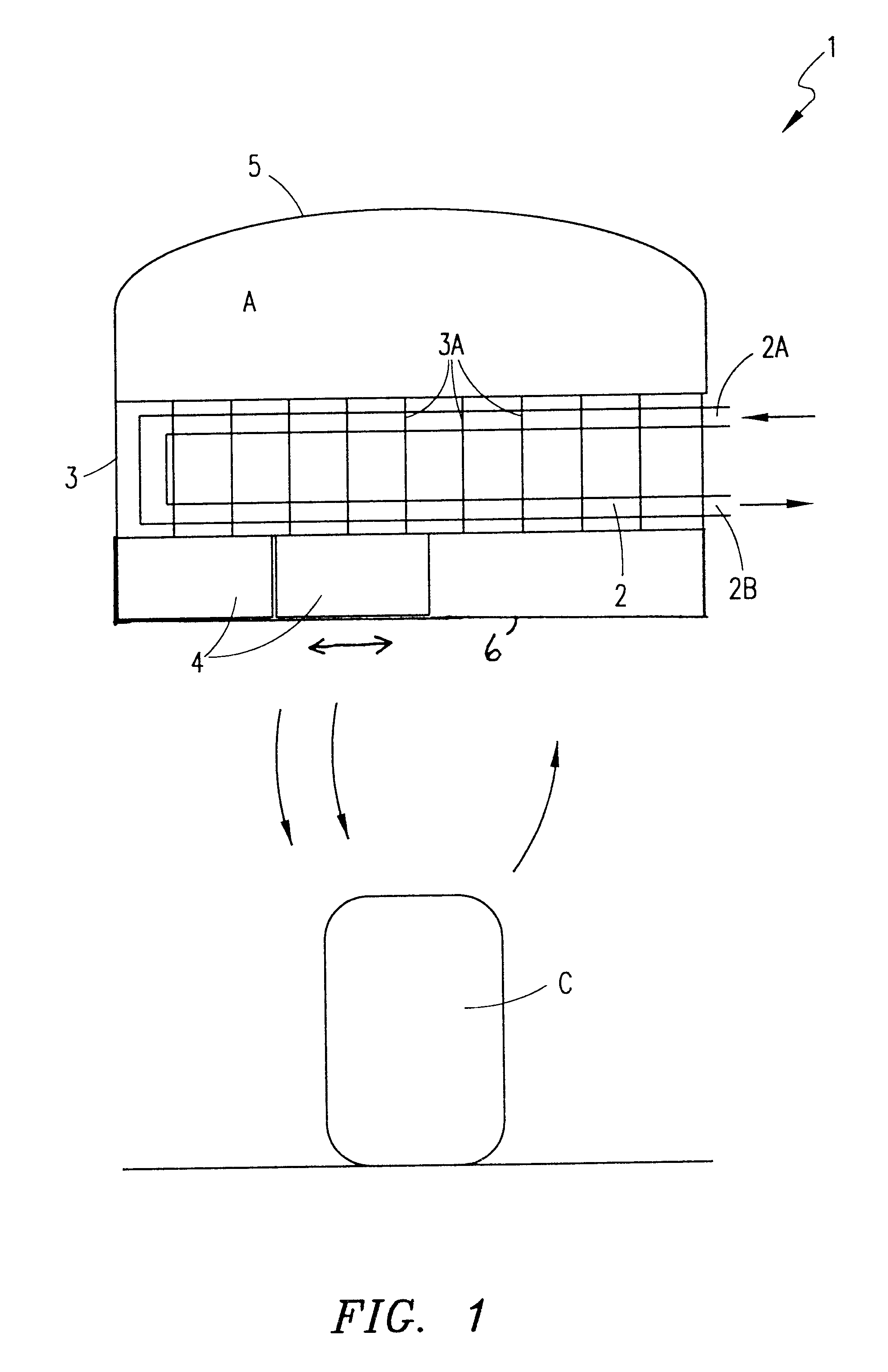
In the present invention, hood assembly 5 is dome-shaped or otherwise includes tapered end portions, as shown in FIG. 1. It is understood, however, that hood assembly 5 may have other shapes.

Cooling system 1 is preferably dimensioned so that cooling system 1 unobtrusively hangs from a ceiling or other structure, without interfering with objects or persons underneath cooling system 1. By way of one example, the combined height of hood assembly 5 and frame member 3 / heat exchanger 2 is approximately 18". It is understood, that the dimensions of cooling system 1, including the height thereof, may vary.

Because the thermal characteristics of heat generating object C may vary over time, such as by moving heat generating object C relative to cooling system 1 or adding equipment to or removing equipment from heat generating object C, it is advantageous to modify the cooling and / or operating characteristics of cooling system 1 accordingly. According to an embodiment of the present invention, ...

second embodiment

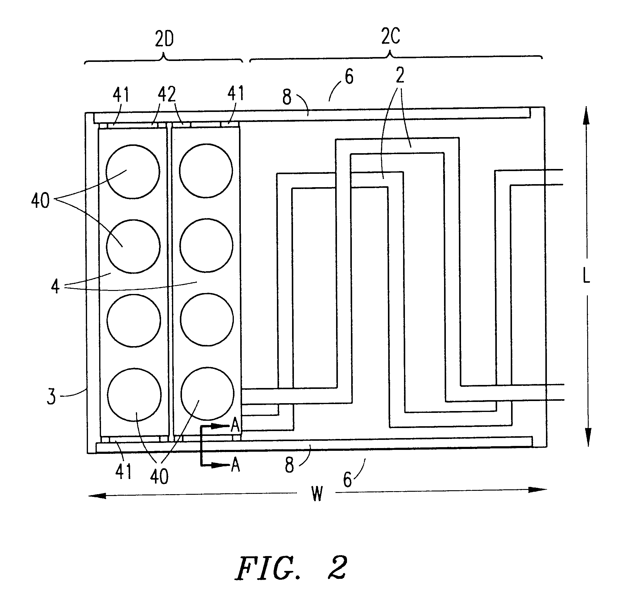
In the present invention, cooling system 100 includes fan units 4 that are disposed between heat exchanger 2 and hood assembly 5 (FIG. 9). In this embodiment, tray members 6 are disposed from one end of cooling system 1 to another. Fan units 4 engage with tray members 6 as described above so that each fan unit 4 is independently positionable along tray members 6. Fans 40 within fan units 4 are operable to blow air that was previously collected along airflow paths 20 within hood assembly 5. Fans 40 blow the collected air through heat exchanger 2 and towards heat generating object C along airflow paths 21. The blown air is thus twice cooled by heat exchanger 2, a first time as the air is being collected and a second time as the air is blown from fan unit 4.


PUM


Abstract

A method and system are disclosed for cooling a heat generating object. A coolant is passed through a heat exchanger so that heated air passing through a first portion of the heat exchanger is cooled. A fan unit is selectively positioned relative to the heat exchanger. When activated, the fan unit draws the cooled air through a second portion of the heat exchanger and directs the twice cooled air towards the heat generating object. The fan unit may be repositioned along a different portion of the heat exchanger so as to redefine the flow of air drawn from and directed towards the heat generating object.

Description

1. Technical Field of the InventionThe present invention relates to cooling systems for cooling electronic equipment, and particularly to systems for cooling electronic equipment that are reconfigurable to allow customized air flow in proximity to the electronic equipment.2. Background and Objects of the InventionThe growth of the computer industry and telephony over the past few decades has been phenomenal. The integration of these technologies, for example, in telecommunications switching systems, has lead to greater and greater efficiencies as larger numbers of communications are handled by fewer components, which are typically housed in a central control room.One problem inherent with many existing cooling systems for electronic equipment is rigidity. Many existing cooling systems are built into and / or under the flooring of a temperature-controlled room having equipment needing to be cooled. Such cooling systems employ fixed conduits or other piping for directing cooled air alon...

Claims


Application Information

Patent Timeline
Patent Type & Authority Patents(United States)
IPC IPC(8): H01L23/40H01L23/467H01L23/34H05K7/20
CPCH01L23/40H01L23/467H05K7/206H01L2924/0002H01L2924/00
Inventor STAHL, LENNARTBELADY, CHRISTIAN
Owner VERTIV CORP
Why Eureka
Try Eureka