Cooling system and method for distributing cooled air

a cooling system and air distribution technology, applied in the field of cooling systems, can solve the problems of significantly reducing system performance, temperature control, electronic equipment, etc., and achieve the effect of greater and greater efficiency

Inactive Publication Date: 2000-12-19
AMERICAN TELEPHONE & TELEGRAPH CO +1
View PDF7 Cites 21 Cited by
  • Summary
  • Abstract
  • Description
  • Claims
  • Application Information

AI Technical Summary

Benefits of technology

The growth of the computer industry and telephony over the past few decades has been phenomenal. The integration of these technologies, for example, in telecommunications switching systems, has lead to greater and greater efficiencies as larger numbers of communications are handled by fewer components, which are typically housed in a central control room.

Problems solved by technology

One problem inherent with all electronic equipment., telecommunications or otherwise, is temperature control.
As is readily apparent, if telecommunications switching equipment or other electronic components are not effectively cooled, the internal temperature of the electronic components substantially increase, thereby leading to significantly reduced system performance and, in some cases, total system failure.
If the cooling system cannot reliably and continuously cool the equipment due to failure of one or more cooling system components, such as cooling system pump units, system failure results.

Method used


Image

  • Cooling system and method for distributing cooled air
  • Cooling system and method for distributing cooled air
  • Cooling system and method for distributing cooled air

Examples


Embodiment Construction

The present invention will now be described more fully hereinafter with reference to the accompanying drawings in which preferred embodiments of the invention are shown. This invention may, however, be embodied in many different forms and should not be construed as limited to the embodiments set forth herein. Rather, these embodiments are provided so that this disclosure will be thorough and complete, and will fully convey the scope of the invention to those skilled in the art.

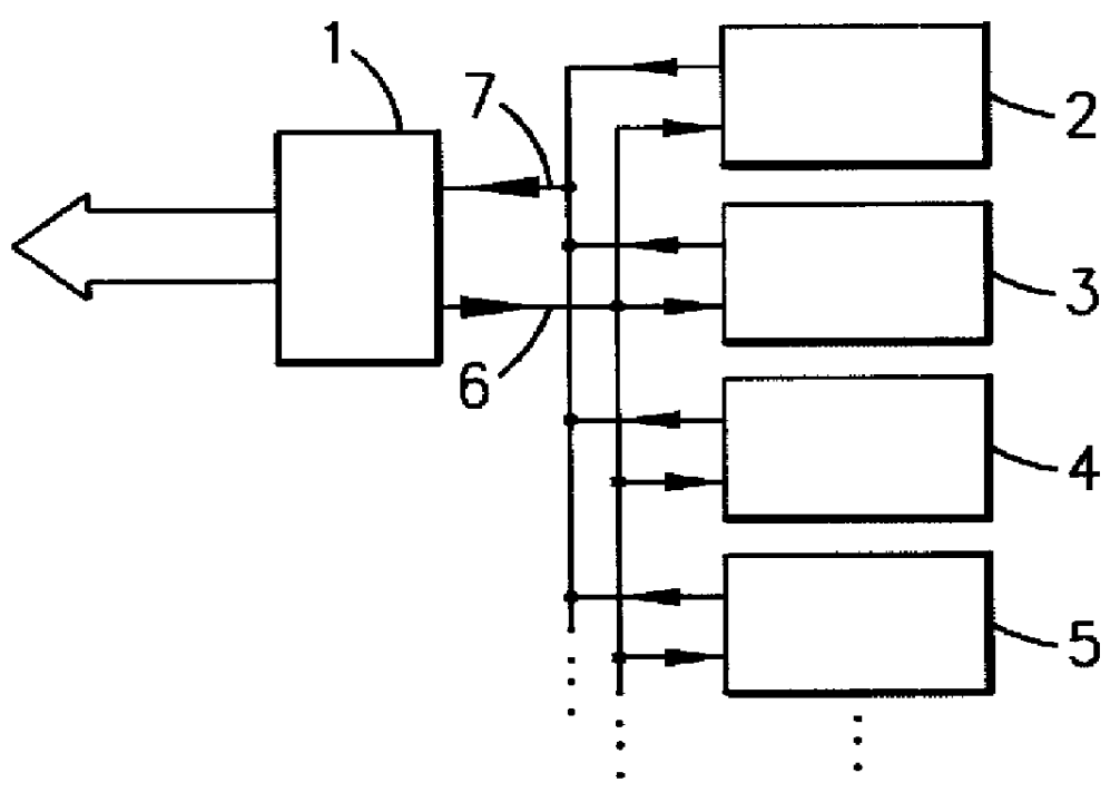
Referring to FIG. 1, there is shown a conventional cooling system in which pump 1 supplies a liquid to heat exchanger units and / or cooling coils 2-5 via a supply line 6 and receives the return liquid via a return line 7. Cooling coils 2-5 are arranged in a row of cooling coils. Pump 1 preferably pumps a cooled liquid into supply line 6 for distributing into cooling coils 2-5. Cooling coils 2-5 are cooled as the cooled liquid flows therethrough. Air directed in relatively close proximity to the cooling coils 2-...


PUM


Abstract

A cooling system employing redundant system components is disclosed. The system includes multiple sets of heat: exchanger units, with each set being in fluid communication with a separate, independently operated fluid pump unit. The heat exchanger units are arranged in at least one row of heat exchanger units. The two sets of heat exchanger units are evenly interspersed with each other along the row of heat exchanger units so that a substantially uniform distribution of cooled air is provided in the event one fluid pump unit fails.

Description

1. Technical Field of the InventionThe present invention relates to cooling systems for cooling electronic equipment, and particularly to cooling systems employing redundancy to maintain desired temperature conditions in the event of system component failure.2. Background and Objects of the InventionThe growth of the computer industry and telephony over the past few decades has been phenomenal. The integration of these technologies, for example, in telecommunications switching systems, has lead to greater and greater efficiencies as larger numbers of communications are handled by fewer components, which are typically housed in a central control room.One problem inherent with all electronic equipment., telecommunications or otherwise, is temperature control. As is readily apparent, if telecommunications switching equipment or other electronic components are not effectively cooled, the internal temperature of the electronic components substantially increase, thereby leading to signifi...

Claims


Application Information

Patent Timeline
Patent Type & Authority Patents(United States)
IPC IPC(8): H05K7/20
CPCH05K7/2059
Inventor ST.ANG.HL, LENNARTWALLACE, JR., JOHN FRANCISPARRAZ, JOHN CARLENASCLARK, MONTFORD HENRYWINN, DAVID
Owner AMERICAN TELEPHONE & TELEGRAPH CO
Why Eureka
Try Eureka