Method for fabricating an electronics board with thermal-conduction cooling

a technology of thermal-conduction cooling and electronics board, which is applied in the direction of total factory control, programme control, electric programme control, etc., can solve the problems of removing the energy dissipated, the integrated circuit is nowadays becoming smaller and smaller, and the functions are increasingly complex

Inactive Publication Date: 2000-03-14
THOMSON CSF SA
View PDF14 Cites 49 Cited by
  • Summary
  • Abstract
  • Description
  • Claims
  • Application Information

AI Technical Summary

Problems solved by technology

In the electronics components sector, integrated circuits are nowadays becoming smaller and smaller, while fulfilling increasingly complex functions.
Problems then arise with removing the energy dissipated as heat during their operation.
The effect of this is that, as the dimensions of the integrated circuits decrease, it becomes increasingly difficult and expensive to resolve the problems posed by thermal dissipation.
A thermal dissipation device of this type is difficult to use in devices which contain a plurality of boards, for example board racks fitted to bay structures.
This is because the boards are generally positioned vertically inside the rack, and the small space between the boards does not allow a dissipative cold plate to be inserted.
Furthermore, because of the ve

Method used


Image

  • Method for fabricating an electronics board with thermal-conduction cooling
  • Method for fabricating an electronics board with thermal-conduction cooling
  • Method for fabricating an electronics board with thermal-conduction cooling

Examples


first embodiment

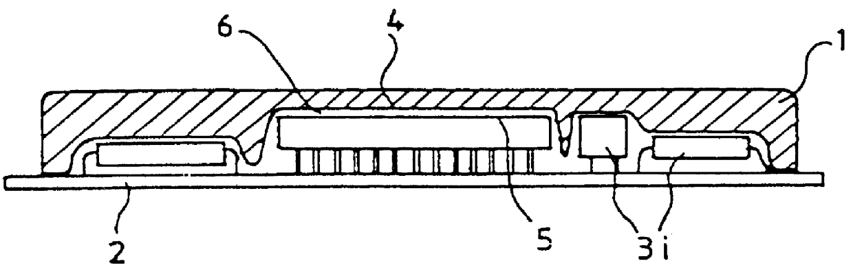
FIG. 2 illustrates a first step of the method according to the invention, during which an impression is taken of the face 5 of the printed circuit 2 and of the components 3i fitted on the printed circuit 2.

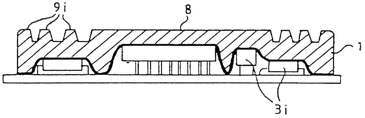
An arbitrary type of commercially available board 2 and 3i, consisting of the printed circuit 2 and the components 3i fitted on the printed circuit 2, may be temporarily coated with a film 10 of small thickness, for example of the order of 0.5 mm. The film 10 is made of a thermoformable rigid material which is preferably also antistatic in order to prevent any electrostatic discharge that might destroy some of the fragile components in contact with the film 10.

In order to deform the film 10, an example of a known technique consists in softening the film 10 which is made of thermoplastic, for example a material such as Macrolon (registered trade mark), polycarbonate, PVC, etc., under the action of a heat source, and at the same time in sucking the film 10 in the direction of the co...

second embodiment

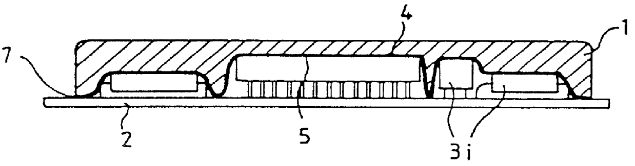
a heat sink according to the invention, illustrated by FIG. 4, consists in directly recording the profile 14, represented by a dashed line, of the face 5 which the printed circuit 2 and the components 3i have, in order to describe the entire surface of the face 5 without employing the intermediary of the film 10.

The position sensor 15 is designed to track the contour of the profile 14. Since the processing of the positional information (X-Y-Z) is then exactly the same as in the first embodiment, it will not be described again. In order to preserve the space 6 which, in the preceding embodiments, corresponds to the thickness of the film 10 and allows mechanical and thermal coupling between the sink 1 and the printed circuit 2 equipped with the components 3i, it is sufficient to provide in the machining programme 13 an offset, for example of 0.5 mm, between the real profile 14 recorded by the sensor 15 and the profile to be machined, corresponding to the face 4 of the sink 1, and a sm...


PUM

PropertyMeasurementUnit
Shapeaaaaaaaaaa
Thermal propertiesaaaaaaaaaa

Abstract

PCT No. PCT/FR96/00150 Sec. 371 Date Aug. 21, 1997 Sec. 102(e) Date Aug. 21, 1997 PCT Filed Jan. 30, 1996 PCT Pub. No. WO96/26631 PCT Pub. Date Aug. 29, 1996Method for fabricating thermally cooled electronic cards. A card of any kind is covered with a rigid heat sink shaped to fit the card and is attached thereto. The heat sink is formed in such a way that it fits as closely as possible the shape of the printed circuit. The printed circuit has components on one or both faces so that it is possible to increase the surface thermal coupling between the sink and the board. An optical sensor using a laser beam may be used.

Description

1. Field of the InventionThe present invention relates to the field of dissipating the heat from electronic components on printed circuits, and its subject-matter is more particularly a method for fabricating an electronics board with thermal-conduction cooling.2. Discussion of the BackgroundIn the electronics components sector, integrated circuits are nowadays becoming smaller and smaller, while fulfilling increasingly complex functions. The rise in the integration density leads to an increase in the density of heat dissipated in the units containing the electronics boards, the physical dimensions of which are still of the same order of magnitude. Problems then arise with removing the energy dissipated as heat during their operation.The effect of this is that, as the dimensions of the integrated circuits decrease, it becomes increasingly difficult and expensive to resolve the problems posed by thermal dissipation. Because of economic problems, the electronics industry, with essenti...

Claims


Application Information

Patent Timeline
IPC IPC(8): G05B19/42H05K7/20
CPCG05B19/4207H05K7/20509G05B2219/49347Y10T29/53174Y10T29/49131Y10T29/4913Y02P90/02
Inventor SUPPA, VITOBEGNIS, NOELALDON, JEAN-CLAUDE
Owner THOMSON CSF SA
Why Eureka
Try Eureka