

Blind hole self-collet countersink
a self-colleting, blind hole technology, applied in the direction of transportation and packaging, manufacturing tools, portable drilling machines, etc., can solve the problems of inability to accurately control the depth of the countersink, the inability to countersink large diameter holes in graphite epoxy and other materials, and the inability to countersink large diameter holes
- Summary
- Abstract
- Description
- Claims
- Application Information
AI Technical Summary
Problems solved by technology
Method used
Image

Examples
Embodiment Construction
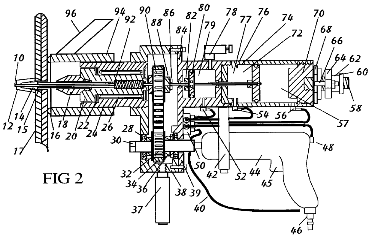
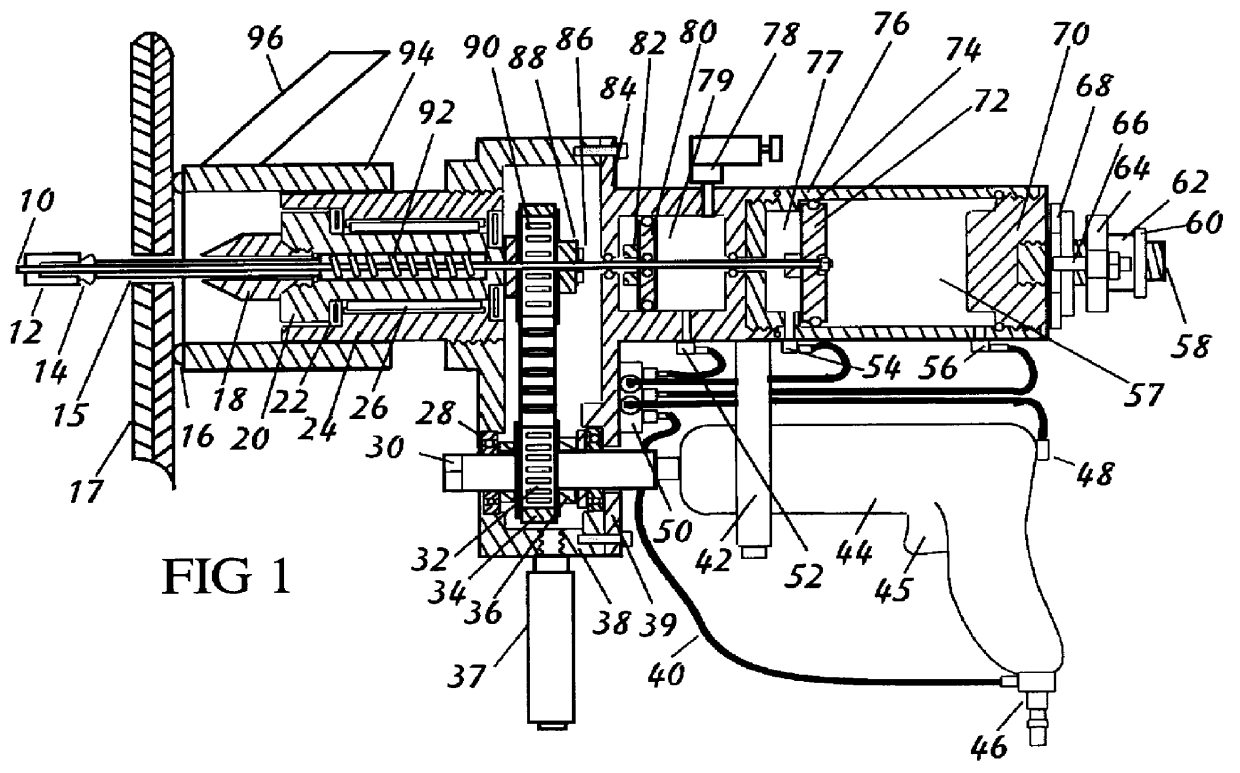
Referring to FIG. 1, a sectional side view of the tool is shown. When the air supply line is attached to an air supply fitting 46 the pneumatic supply line 40 activates the air splicer block 50 and supplies air pressure to air supply fitting 52 and air supply fitting 56. The piston return cylinder 57 and feed rate cylinder 79 are now pressurized, which sets both body piston 72 and spindle piston 80 into their start positions. Spindle piston 80 reacts against spindle bar 82 which is attached to nose 94 and holds nose 94 at its outermost limit. This has clamped the tool to the workpiece 17.
As is best seen in FIG. 2, after the operator inserts the tool into a previously drilled hole 15 in workpiece 17, the tool is ready to countersink. By activating the drill motor trigger 45, air pressure in piston return cylinder 57 is vented off through the air supply fitting 56. The pressure remains in feed rate cylinder 79. The drill motor 44 starts rotating the motor shaft pulley 32 and transferr...
PUM
| Property | Measurement | Unit |
|---|---|---|
| Pressure | aaaaa | aaaaa |
| Depth | aaaaa | aaaaa |
Abstract
Description
Claims
Application Information