Vacuum stretching and gripping tool and method for laying flooring

a vacuum stretching and flooring technology, applied in the direction of floor fabrics, wire tools, construction, etc., can solve the problems of not being able to achieve the necessary smoothing, the device is no longer useful, and the problem of presenting unique and challenging problems, so as to effectively clamp the suction cup

Inactive Publication Date: 2000-03-21
SMITH MARK
View PDF34 Cites 36 Cited by
  • Summary
  • Abstract
  • Description
  • Claims
  • Application Information

AI Technical Summary

Benefits of technology

Viewed from a third vantage point it is the object of the present invention to provide a method of stretching a smooth floor covering over a substrate, the method comprising the steps of: coupling an end of the floor covering to the substrate; mounting a vacuum pump operated suction cup equipped with a pusher plate on a selected surface of the covering; evacuating the suction cup to effectively clamp the suction cup to the covering; mounting an extendible jack between the pusher plate and a stationary reaction surface; and extending the jack to move the suction cup and attached covering with respect to the reaction surface.

Problems solved by technology

Once the frictional limitation of the device is met, this device is no longer useful.
So that, if more stretching is required than this device can frictionally accommodate, necessary smoothing cannot be accomplished.
Installers of all types of floor covering know that the installation of vinyl or similar floor covering presents some unique and challenging problems which require special skills.
The main problem arises from the need to employ a relatively quick setting adhesive to bond the flooring sheet to the floor, and the inability of any trapped air to bleed through the flooring.
When the flooring sheet is cut and placed over the adhesive, air is trapped in certain locations forming ripples and blisters.
The process is conducted in a hit or miss manner, leaving behind hidden air pockets which may lead to cracking and unsightly bumps.
Many times, the prior art devices are simply incapable of correcting the anomalies due to their lack of sufficient frictional gripping means.
Vinyl, being less pliable and far less porous to air than, for instance, carpeting, is more difficult to lay flat, particularly over a tacky adhesive surface.
This is especially difficult, if not previously impossible to overcome, when the vinyl has been distorted from shipping or being warehoused for a long period of time in a roll at the bottom of a pile of rolls and hence has become permanently deformed.
However, if the anomaly is too severe, these old devices will not overcome the anomaly.
In these cases, installers will many times return the flooring material to the supplier as "unusable".
This was neither known, nor possible, in the past.

Method used


Image

  • Vacuum stretching and gripping tool and method for laying flooring
  • Vacuum stretching and gripping tool and method for laying flooring
  • Vacuum stretching and gripping tool and method for laying flooring

Examples


first embodiment

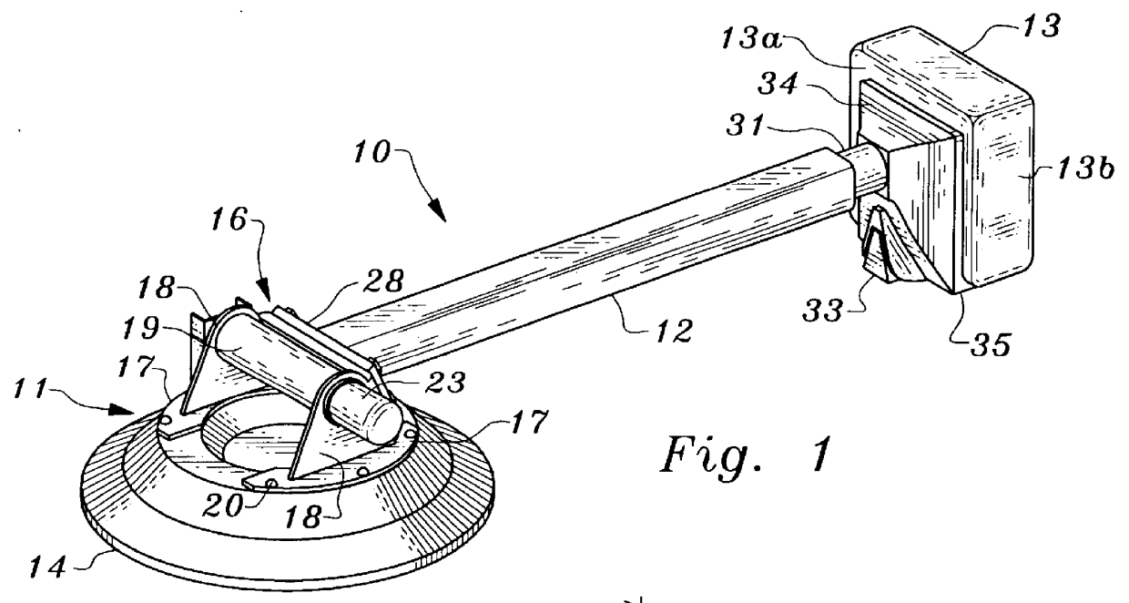
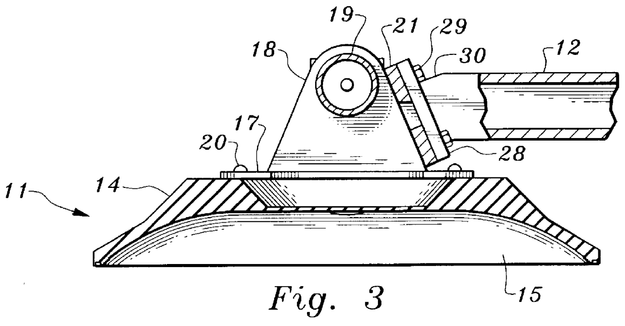
Considering the drawings, wherein like reference numerals denote like parts throughout the various drawing figures, reference numeral 10 is directed to a flooring vacuum stretcher according to the present invention. The vacuum stretcher is formed of three main components; a vacuum head 11, an adjustable handle 12, and a knee pad 13. The vacuum head 11 comprises a vacuum pad or suction cup 14 made of pliant rubber or any suitable elastomer having equivalent properties. An air space or chamber 15 is formed in the inverted suction cup 14 and when the air is evacuated, the suction cup 14 collapses by the action of atmospheric pressure and seals against a smooth surface as best shown in FIG. 5.

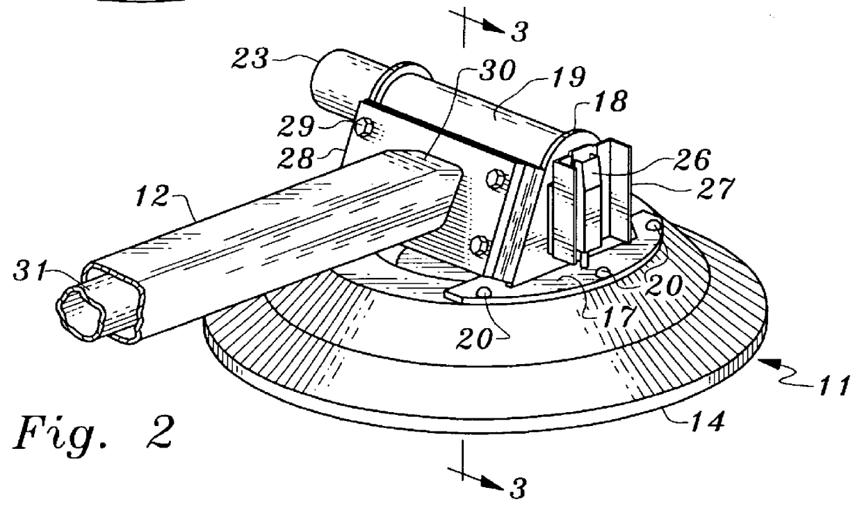
A superstructure 16 formed of two spaced flanges 17 with upstanding angled ears 18 connected by a cross tube 19 is securely attached to the suction cup 14 by means of fasteners 20. As best shown in FIGS. 7 and 8, a mounting or pusher plate 21 having a rectangular opening 22 is secured to the angled...

second embodiment

In the invention illustrated in FIGS. 8-13, a toggle jack 42 is provided with a jack head 43 having a tapered drive 44 which is inserted in rectangular opening 22 in pusher plate 21. The jack head 43 has a pair of upstanding ears 45 which pivotally supports a jack handle 46.

The toggle jack 42 comprises a main cylinder 47 which by telescoping receives a jacking cylinder 48 welded or brazed to jack head 43. A pair of toggle links 49 each have one end pivoted to main cylinder 47 at 50 and another end pivoted to handle 46 at 51. By raising the handle 46 as shown in FIG. 12 jacking cylinder 48 is telescoped within the main cylinder 47 and the jack head 43 is withdrawn placing the jack 42 in a loaded position. FIG. 13 shows the toggle jack 42 after it has completed a power stroke. Lowering handle 46 causes it to pivot around pivots 51 acting as a fulcrum with increased leverage supplied by the toggle links 49 to force the jacking cylinder 48 and jack head 43 into an extended position. In ...


PUM


Abstract

A vacuum pump operated suction cup is utilized to form tools to assist the installer in laying flooring. In one embodiment, the suction cup is provided with a bracket which supports the vacuum pump and a handle having a knee pad at the end. In use, the suction cup is vacuum bonded to the flooring and pressed against the floor by hand while the knee pad is kicked with the knee to smooth out any irregularities. In another embodiment the flooring is stretched by pushing the vacuum bonded suction cup with a jack. In another embodiment, a tacking strip is utilized in lieu of adhesive to secure the flooring to a substrate with the assistance of the vacuum pump.

Description

This invention relates to tools and their application to laying floor coverings configured as sheet goods.The following prior art reflects the state of the art of which applicant is aware and is included herewith to discharge applicant's acknowledged duty to disclose relevant prior art. It is stipulated, however, that none of these references teach singly nor render obvious when considered in any conceivable combination the nexus of the instant invention and as particularly claimed.U.S. Pat. No. 5,516,170 discloses a vinyl and carpet kicker having interchangeable face plates so as to enable the tool to be used both in laying carpets and vinyl floor covering. When working with vinyl, a face plate is used having numerous small downwardly directed pyramidal knobs for frictional engagement with the vinyl surface. The knee kicker at the rear of the handle is provided with a wheel to reduce friction as the tool is moved along the vinyl surface. The disclosed tool can be used to smooth and...

Claims


Application Information

Patent Timeline
Patent Type & Authority Patents(United States)
IPC IPC(8): E04F21/22E04F21/00
CPCE04F21/22
Inventor SMITH, MARK
Owner SMITH MARK
Why Eureka
Try Eureka