Method for providing two modes of I/O pad termination

a technology of i/o pad and termination mode, which is applied in the direction of logic circuits, pulse techniques, and increasing modifications, etc., can solve the problems of reducing and affecting the performance of the computer system

Inactive Publication Date: 2000-03-21
MICRON TECH INC
View PDF8 Cites 57 Cited by
  • Summary
  • Abstract
  • Description
  • Claims
  • Application Information

AI Technical Summary

Problems solved by technology

As computer systems require faster data transfer speeds between integrated circuits, the TTL and LVTLL interface standards are beginning to limit computer system performance.
For example, the delay time in charging and discharging a typical 100 pF capacitance between the 2.4 and 0.4 volt thresholds is beginning to exceed required access times. Additionally, as switching speeds increase, the output waveform of a TTL or a LVTTL driver becomes distorted due to overshooting, undershooting, ringing and the like, resulting in erroneous level determinations.
The extra computer system components required for GTL communications add significantly to system cost.
However, for cheaper computer systems,--especially sub-$1000 personal computers--people may be unwilling to pay the additional costs.
Additionally, economies of scale make it expensive and impractical to produce two different microprocessor chips, one supporting a GTL interface and the other supporting a TTL or a LVTTL interface.
Hence, Konishi does not disclose a method and an apparatus for eliminating a bus termination.
Furthermore, Konishi discloses a complicated apparatus in which a pullup transistor is converted into an additional pulldown transistor, and Konishi does not disclose a slew rate control circuit, or a turn-off control circuit.

Method used


Image

  • Method for providing two modes of I/O pad termination
  • Method for providing two modes of I/O pad termination
  • Method for providing two modes of I/O pad termination

Examples


Embodiment Construction

of the Output Driver

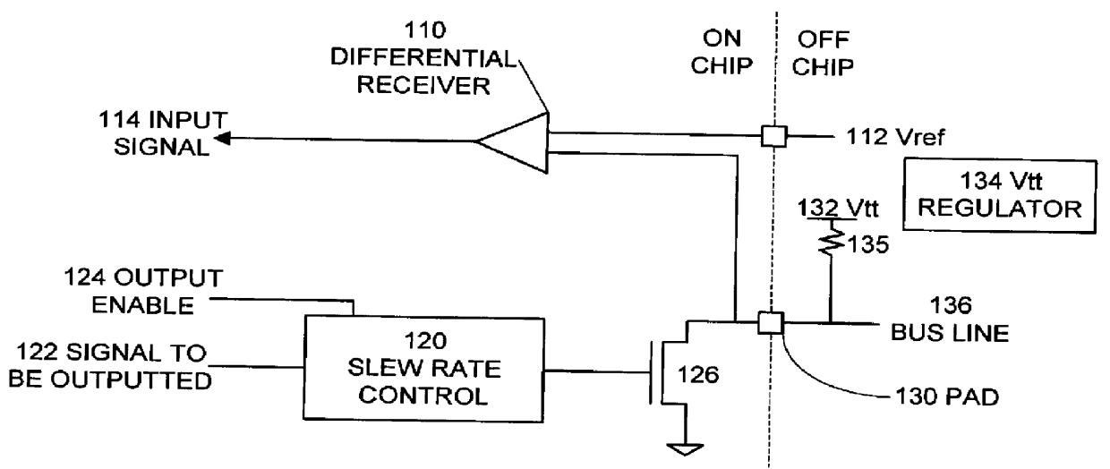
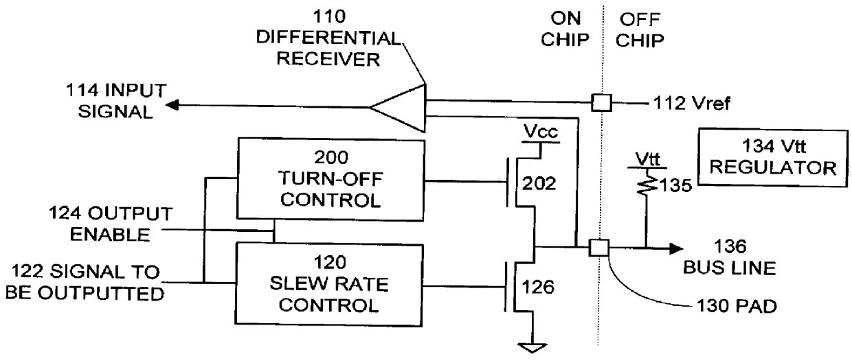
FIG. 6 illustrates a dual mode output circuit in accordance with an embodiment of the present invention. The circuitry illustrated in FIG. 6 is the same as the circuitry illustrated for the enhanced GTL+ driver in FIG. 2, except that turn off control circuit 200 has been replaced with mode select circuit 600. In addition to receiving inputs from signal to be outputted 122 and output enable signal 124, mode select circuit 600 takes an input from mode select signal 602. When mode select signal 602 indicates the open drain mode, transistor 202 can still drive active turnoff, in which transistor 202 may be active for one clock cycle. However, in open drain mode transistor 202 is disabled from holding the bus to a high voltage. When mode select signal 602 indicates the totem pole output mode, mode select circuit 600 activates transistor 202 whenever the signal to be outputted 122 is asserted to a high value and output enable signal 124 is asserted. In this way, the em...


PUM


Abstract

The present invention provides a method of providing two different modes of operation for an output driver on an integrated circuit. A first mode provides an open drain driver, such as an enhanced GTL+ driver, for high-speed data transmission. A second mode provides a totem pole output driver, such as a TTL or a LVTLL driver, which does not require additional circuitry for external terminations, as is required for open drain drivers. Thus, one embodiment of the present invention can be characterized as a method of providing a dual mode output from an integrated circuit. This method includes receiving an output mode signal indicating an enhanced GTL+ output mode or a totem pole output mode. This method also includes providing an enhanced GTL+ output signal if the mode signal indicates the enhanced GTL+ output mode, and providing a totem pole output signal if the mode signal indicates the totem pole output mode. Another embodiment of the present invention can be described as a method for providing a dual mode output from an integrated circuit. This method includes providing to the integrated circuit an output mode signal indicating a first output mode or a second output mode. It also includes coupling an output pin of the integrated circuit to an open drain bus with an active termination if the mode signal indicates the first mode, and coupling an output pin of the integrated circuit to an unterminated bus if the mode signal indicates the second output mode.

Description

1. Field of the InventionThe present invention relates to the design of input / output (I / O) circuits for semiconductor chips, and more specifically to the design of an I / O circuit that provides two output modes. In a first mode, the output is tailored to drive an open drain bus, which requires an external termination on a bus line. In a second mode, the output functions as a totem pole output, which does not require an external termination.2. Related ArtUntil recently, transistor--transistor logic (TTL) has been the dominant interface standard for semiconductor integrated circuits. Under the TTL standard, an input or an output of at least 2.4 volts corresponds to a logic "1," whereas an input of not more that 0.8 volts and an output of not more than 0.4 volts corresponds to a logic "zero." However, following the recent reduction of power source voltages in semiconductor devices (for example, from 5 volts to 3.3 volts), a reduced voltage version of TTL has emerged, which is known as L...

Claims


Application Information

Patent Timeline
Patent Type & Authority Patents(United States)
IPC IPC(8): H03K19/0185
CPCH03K19/018585
Inventor KLEIN, DEAN A.
Owner MICRON TECH INC
Why Eureka
Try Eureka