Shaving or cutting instrument

a cutting instrument and blade technology, applied in the field of shaving or cutting instruments, can solve the problems of severed tissue particles being stuck in the narrow gap between the inner and outer blades, the risk of soiling, and the blade "clogging" and/or transfer of tissue particles,

Inactive Publication Date: 2000-03-28
KARL STORZ ENDOSCOPY AMERICA
View PDF9 Cites 179 Cited by
  • Summary
  • Abstract
  • Description
  • Claims
  • Application Information

AI Technical Summary

Problems solved by technology

The known removal or cutting instruments involve, however, the problem that abraded or cut-off tissue particles may adhere to the blade and hence induce the risk of soiling, of blade "clogging" and/or transfer of tissue particles.
With these instruments

Method used


Image

  • Shaving or cutting instrument
  • Shaving or cutting instrument
  • Shaving or cutting instrument

Examples


Embodiment Construction

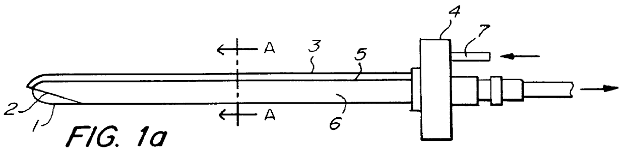
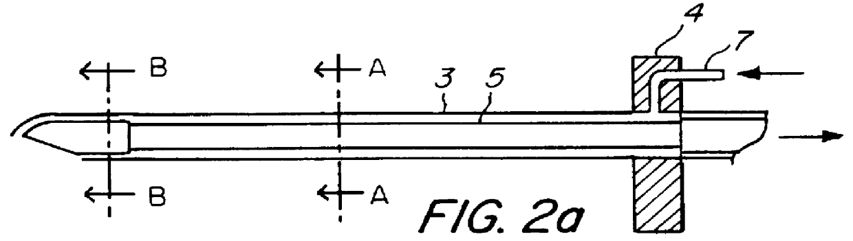
The inventive instrument illustrated in FIG. 1a comprises an inner blade 1 and an outer blade 2 in a manner known per se. The outer blade 2 is stationary and in the embodiment shown here it is connected to a proximal body portion 4 of the instrument. The inner blade 1 is connected via a tube 5 supported for rotation to a drive unit which is not illustrated here and which rotates the inner blade 1 relative to the main body portion 4 and hence to the stationary outer blade 2. A suction or exhaust passage 6 is provided in the tube 5, which is connected by its distal end to an appropriate suction pump not illustrated here.

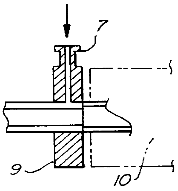
In the embodiment shown here an additional irrigation passage is provided through which an irrigation pump (not illustrated) pumps an irrigation liquid from a fitting 7 to the distal end. In the embodiment illustrated here the irrigation passage 8 is mounted on the tube 3 of the outer blade 2. FIGS. 1b and 1c, which illustrate a section taken at A--A in FIG. 1a, repres...


PUM


Abstract

PCT No. PCT/DE96/02213 Sec. 371 Date Jul. 16, 1998 Sec. 102(e) Date Jul. 16, 1998 PCT Filed Nov. 20, 1996 PCT Pub. No. WO97/18745 PCT Pub. Date May 29, 1997A cutting apparatus is provided with both a rotating inner blade and a stationary outer blade at its distal end and is connected to a drive unit disposed in the proximal region. The outer blade is spaced from the inner blade to form an irrigation passage through which an irrigation liquid is passed. A flushing duct is provided for fluid communication to the distal end. Additionally, a suction passage is provided to exhaust tissue particles.

Description

The present invention relates to an abrasive or cutting instrument with a rotating blade having an abrasive or cutting region at its distal end in accordance with the introductory clause of Patent claim 1.Such abrasive or cutting instruments, which are also termed scrapers or rasps, are employed in endoscopic surgery, e.g. in micro arthroplasty operations.PRIOR ARTShaving or cutting instruments of the claimed general type include at least one blade which is rotated at a speed of up to 1,600 or more revolutions per minute. To this end the blade is connected via a shaft to a motor accommodated in the proximal section of the instrument.The shaft may be a hollow shaft. The passage formed by this configuration is connected to a suction opening in the face area of the blades, which present normally a cylindrical configuration. In this manner it is possible to exhaust liquid and severed tissue particles through the blade.The known removal or cutting instruments involve, however, the proble...

Claims


Application Information

Patent Timeline
IPC IPC(8): A61B17/32A61M1/00
CPCA61B17/32002A61B2217/005A61B2217/007
Inventor STORZ, DECEASED, KARLNOVAK, PAVELSOLINGEN, SIMON
Owner KARL STORZ ENDOSCOPY AMERICA
Why Eureka
Try Eureka