
Limited scan phased array antenna

Inactive Publication Date: 2000-03-28
SENSIS CORPORATION
View PDF14 Cites 19 Cited by
  • Summary
  • Abstract
  • Description
  • Claims
  • Application Information

AI Technical Summary

Benefits of technology

Another object of the present invention is to provide a limited scan phased array system that requires a much fewer number of phase controls than are required by a conventional array antenna.
Still another object of the present invention is to provide a low sidelobe element pattern that suppresses grating lobes well below -20 dB with array scanning.
It is a related object to provide an element amplitude taper, for low element sidelobes, without incurring a taper efficiency loss in addition to the element gain loss as the array beam is scanned off broadside.

Problems solved by technology

This design approach is much too expensive for most limited scan applications because of the large number of elements and phase shifters involved.

Method used


Image

  • Limited scan phased array antenna
  • Limited scan phased array antenna
  • Limited scan phased array antenna

Examples


Embodiment Construction

The following description relates to specific embodiments of the present invention, though it will be readily apparent to those of sufficient skill in the art that other modifications and variations are possible which employ the concepts described herein.

Element Lattice

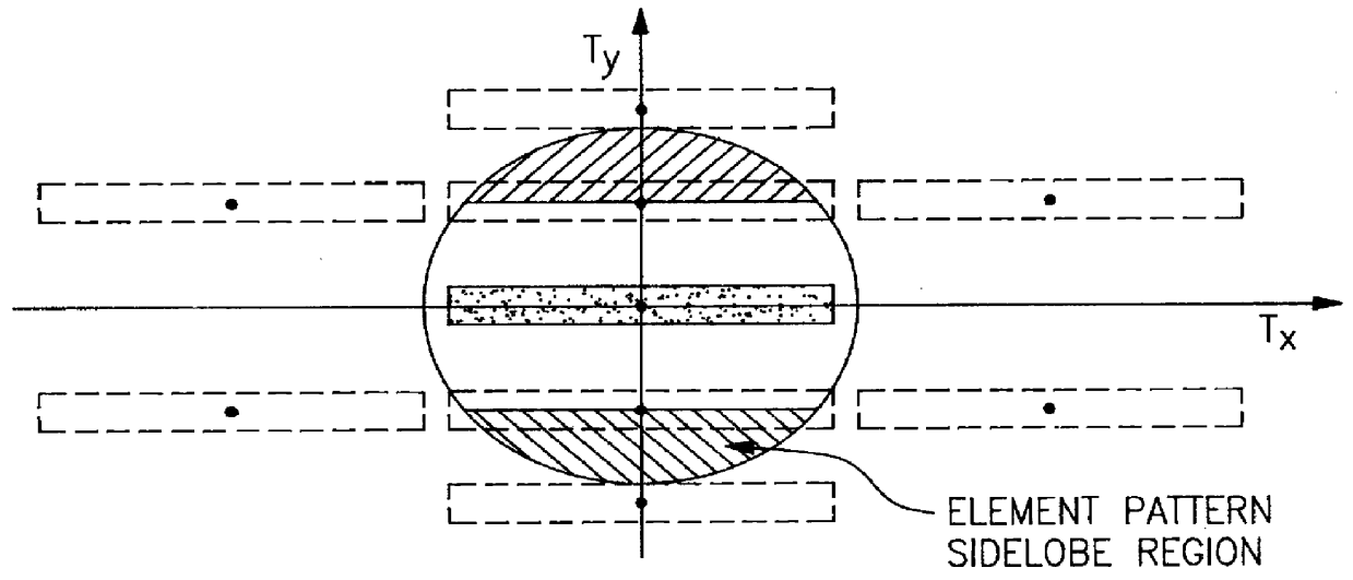
With reference to the drawings, and more particularly to FIG. 1, there is shown a T-plane plot for a rectangular array element lattice 0.905.lambda. in height by 0.53.lambda. in width. Tx and Ty coordinates represent the direction cosines of points in space, for a right-handed coordinate system, with the z-axis normal to the aperture. The hemisphere of visible space forward of the aperture is bounded on the T-plane by a unit circle. It may be shown that the transformation from azimuth (.alpha.) and elevation (.epsilon.) angles of a point in space to the T-plane is given by the equations

Tx=-cos(.epsilon.)sin(.alpha.) (1)

Ty=-sin(.epsilon.)cos(.epsilon..sub.o)-cos(.epsilon.)sin(.epsilon..sub.o)cos(.alpha.) (2)

where .epsi...


PUM


Abstract

A phased array antenna is designed for scanning a narrow beam over an angular sector that is wide in one plane, and narrow in another, while using a minimum number of phase steering controls. High directivity elements occupy a rectangularly shaped area which is large in one direction relative to a second direction, the elements being staggered in position with neighboring elements to suppress near-in grating lobes. The elements are independent and identical to one another so that conventional array beamforming techniques may be utilized.

Description

This invention relates to limited scan phased array antenna systems. More particularly, it relates to scanning the beam of a two-dimensional array antenna over a limited angular extent of only a few beamwidths in one plane (typically elevation) but over a wide angular sector of many beamwidths in the orthogonal plane.DESCRIPTION OF THE PRIOR ARTConventional phased arrays, designed for wide angle scanning, require element spacings of approximately one-half wavelength to avoid the undesired formation of grating lobes within visible space. Even for a limited scan in one plane, this requirement limits the element spacing to less than one wavelength. This design approach is much too expensive for most limited scan applications because of the large number of elements and phase shifters involved. As a result, a number of techniques have been devised to suppress the grating lobes that form in visible space as a result of using element spacings that are large in terms of a wavelength. Exampl...

Claims


Application Information

Patent Timeline
IPC IPC(8): H01Q3/26H01Q21/22
CPCH01Q3/26H01Q21/22
Inventor KINSEY, RICHARD R.
Owner SENSIS CORPORATION
Learn More