Four wheel drive transfer case controller compatible with a spare tire

a transfer case controller and spare tire technology, applied in the field of electric powertrain controllers, can solve the problems of unattainable four-wheel drive vehicles, unacceptable drivability, and increased complexity of the drive train required to control and deliver power to all four wheels,

Inactive Publication Date: 2000-04-04
FORD GLOBAL TECH LLC
View PDF16 Cites 26 Cited by
  • Summary
  • Abstract
  • Description
  • Claims
  • Application Information

AI Technical Summary

Problems solved by technology

Four-wheel drive vehicles provide traction often unattainable in two-wheel drive vehicles by delivering power to each of the vehicle's four wheels.
Attendant with the added traction provided by four wheel drive is the added complexity of the drive train required to control and deliver power to all four wheels as opposed to only two wheels.
The torque transfer to the "nonslipping" wheels causes the differential to cycle excessively and may create a situation where the driveline binds up, creating unacceptable drivability issues as well as potential driveline damage.
These concerns are particularly evident in full time four wheel drive systems, where the operator of the vehicle cannot select two wheel drive when a spare tire used.
Rapid release of the limited slip device to prevent bindup may lead to an extended cycling condition, which in turn may produce NVH problems and durability concerns in the limited slip device.
The inventors herein have recognized that known transfer case control systems experience problems particularly when a tire having a smaller rolling radius is used.
Furthermore, the low pass filtered value is limited so the drivetrain may be controlled to provide torque when the wheels are slipping at a low rate of slip buildup such as in sand.

Method used


Image

  • Four wheel drive transfer case controller compatible with a spare tire
  • Four wheel drive transfer case controller compatible with a spare tire
  • Four wheel drive transfer case controller compatible with a spare tire

Examples


Embodiment Construction

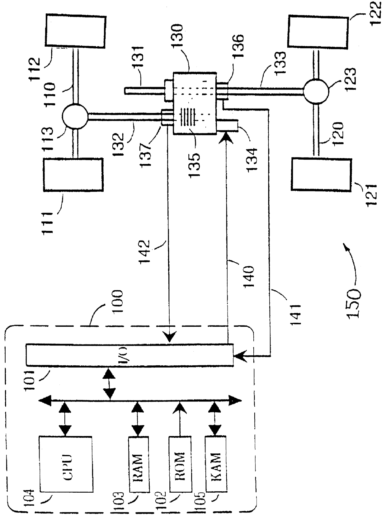
In FIG. 1 of the drawings, a powertrain controller 100 controls the operation of a transfer case 130 of a four-wheel drive vehicle 150. The powertrain controller 100 preferably includes a central processing unit 104, a read-only memory (ROM) 102 for storing control programs, a random-access memory (RAM) 103 for temporary data storage, a keep-alive-memory (KAM) 105 for storing learned values, a conventional data bus and I / O ports 101 for transmitting and receiving signals to and from the transfer case 130.

The transfer case 130 includes an electronically controlled clutch 135 for transferring motive power from an input shaft 131, which transmits power from an engine transmission (not shown), to a front driveshaft 132 and a rear driveshaft 133, in response to a clutch Pulse Width Modulated (PWM) signal 140 generated by powertrain controller 100. The transfer case 130 preferably takes a form as described in U.S. Pat. No. 4,718,303, to Mark J. Fogelberg, entitled "Four Wheel Drive Transf...


PUM


Abstract

A method of monitoring the relative effective diameters of the tires and compensating therefor in a vehicle which includes a front driveshaft for transferring motive power to a front set of wheels and a rear driveshaft for transferring motive power to a rear set of wheels, each of the wheels having an effective diameter. Front and rear driveshaft values indicative of the rotational speed of each driveshaft are generated. A difference value indicative of a difference between said front and rear driveshaft values is then generated. A low pass filtered value is generated according to the relationship of Y1p=(1- beta )*U(k)+ beta *Y1p(k-1). The low pass filtered value is monitored for a predetermined period of time to determine if one of the wheels has a smaller effective diameter than the other wheels.

Description

1. Field of the InventionThis invention relates to the field of electronic powertrain controllers, and more particularly to the field of four-wheel drive vehicles which utilize an electronic powertrain controller.2. Discussion of the Prior ArtFour-wheel drive vehicles provide traction often unattainable in two-wheel drive vehicles by delivering power to each of the vehicle's four wheels. Attendant with the added traction provided by four wheel drive is the added complexity of the drive train required to control and deliver power to all four wheels as opposed to only two wheels. For instance, it is desirable to alter the delivery of power to the front wheels and the rear wheels depending upon whether the vehicle is turning, or is being driven on low traction surfaces such as rain or ice covered surfaces to eliminate relative slip between the front and rear tires. During a situation where wheel slippage is detected, torque is transferred to the nonslipping wheels to maximize traction....

Claims


Application Information

Patent Timeline
Patent Type & Authority Patents(United States)
IPC IPC(8): B60K23/08B60K28/16G01P3/56G01P3/50G01P3/42G01B7/12
CPCB60K23/0808B60K28/16G01P3/56G01B7/12G01P3/50B60T2201/14B60T2240/08B60W2530/20B60W2520/28B60W2050/0052
Inventor RODRIGUES, ASHOKGLAB, JOHN
Owner FORD GLOBAL TECH LLC
Why Eureka
Try Eureka