Low-profile dome-shaped multi-lens system

a multi-lens, low-profile technology, applied in the direction of optical radiation measurement, instruments, nuclear engineering, etc., can solve the problem of difficult to determine a precise motion detection at the peripheral sensitive areas

Inactive Publication Date: 2000-04-18
MATSUSHITA ELECTRIC WORKS LTD
View PDF1 Cites 31 Cited by
  • Summary
  • Abstract
  • Description
  • Claims
  • Application Information

AI Technical Summary

Problems solved by technology

The difference becomes more critical as the sensitive areas are distributed over a wider angular range, which makes it diffi

Method used


Image

  • Low-profile dome-shaped multi-lens system
  • Low-profile dome-shaped multi-lens system
  • Low-profile dome-shaped multi-lens system

Examples


first embodiment

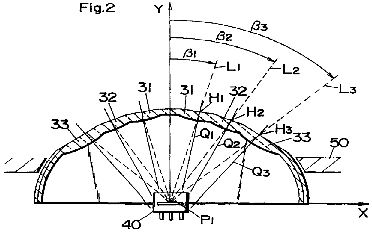
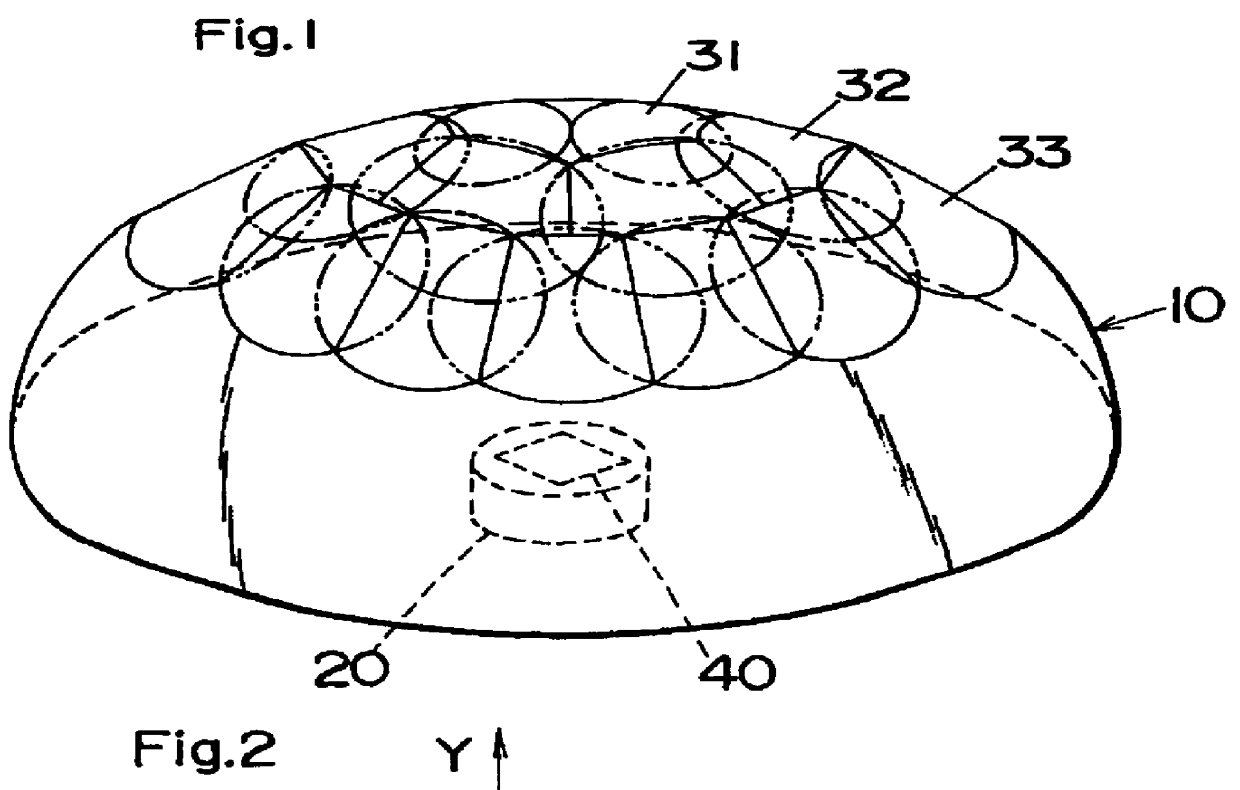
Referring now to FIGS. 1 and 2, there is shown a multi-lens system in accordance with a first embodiment of the present invention. The system comprises a dome-shaped shell 10 with a plurality of convex lenses 31, 32, and 33 which provide a wide panoramic field of view from a focal region 20 in which an optical detector 40 is disposed for receiving infrared radiation through the individual lenses.

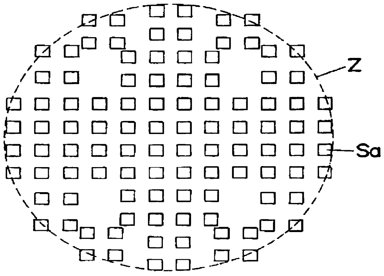
As shown in FIG. 3, the optical detector 40 comprises two pairs of sensing elements 41 and 42 of square configuration and opposite polarity arranged in a square matrix on a radiation receiving surface of the detector 40. The sensing elements are of 0.5 mm square and spaced by 0.5 mm from each other to give output indicative of intensity of the infrared radiation received through the lenses to a known electric circuit for motion detection based upon the fluctuation of the intensity of the infrared radiation. The sensing elements 41 and 42 of opposite polarity give outputs of opposite polarity...

second embodiment

Referring to FIGS. 11 and 12, there is shown a multi-lens system in accordance with a second embodiment of the present invention. The lens system of this embodiment is identical in configuration and operation to the first embodiment except that the outer surface of a dome-shaped shell 10A is formed as a smoothly curved surface coincidence with an ellipsoidal surface. Thus, the lenses 31A, 32A, and 33A are of biconvex configuration defined by the common outer curved surface and different inner curved surfaces. A like optical detector 40A is disposed at a center of the ellipse as in the first embodiment.

third embodiment

FIGS. 13 and 14 show a multi-lens system in accordance with a third embodiment which is similar to the first embodiment except that a domed-shell 10B is of a spherical configuration having an outer curved surface 11B coincident with a part of a sphere having a spherical center C. A like optical sensor 40B is located at a position offset from the center C towards a vertex of the shell 10B. As shown in FIGS. 13 and 14, the lenses 31B, 32B, and 33B have the respective principal points H1, H2 and H3 located on a spherical plane 11B of the shell 10B at different angles about a common point P1 on the optical detector 40B so that the lenses at a greater angular disposition is spaced by a greater distance from the common point P1. In detail, the outer surface 11B of the shell 10B has a radius (r) of 10.13 mm from the spherical center C, and the common center P1 is offset by a distance (d) of 3.62 mm from C towards the vertex. The focal lengths f1, f2 and f3 of the lenses 31B, 32B and 33B ar...


PUM


Abstract

A multi-lens system provides a plurality of sensitive areas of even size over a wide panoramic field of view and reduces an exposure height of the system above an installation plane, yet assuring successful motion detection. The system has a dome-shaped shell with a plurality of convex lenses for collecting infrared radiation from the panoramic field of view to an optical detector positioned in a focal region. The lenses are distributed over a wide solid angular range to give the discrete sensitive areas. The focal region is offset towards a vertex of the shell from a point where optical axes of the outermost lenses at a maximum solid angle about the center axis intersect with each other. Thus, the outer lens at a greater angular disposition has a greater distance to the detector so that it could define its own sensitive area closer in size to the adjacent sensitive area defined by the adjacent lens at a less angular disposition, enabling to equalizing the discrete sensitive areas. Further, the exposure height of the system i.e., a vertical distance between the vertex of the shell and the outermost lens is reduced to achieve a low-profile installation design. The lens at a greater angular disposition about the center axis is set to have a greater focal length so as to provide an effective image spot in the focal region for detection of infrared radiation through each lens by the detector, thereby assuring a consistent motion detection over a widely distributed sensitive areas.

Description

1. Field of the InventionThe present invention is directed to a low-profile dome-shaped multi-lens system, more particularly to such a system for collecting infrared radiation from a panoramic field of view to an optical detector for motion detection.2. Description of the Prior ArtU.S. Pat. No. 4,930,864 discloses a prior lens system covering a panoramic field of view for infrared motion detection within a wide detection range. The system comprises a semispherical shell provided with a plurality of convex lenses arranged to define a plurality of sensitive areas in the panoramic field of view for collecting infrared radiation from each sensitive area to an optical detector. Upon receiving infrared radiation from persons or objects passing through the sensitive areas, the optical detector provides a signal of fluctuating radiation level which is processed by an associated electronic circuitry for detecting a motion of the persons or objects. This lens system is designed to give an equ...

Claims


Application Information

Patent Timeline
IPC IPC(8): G02B3/00
CPCG02B3/0043G02B3/0056Y10S250/01
Inventor KIRIHATA, SHINJIUCHISAWA, KATSUHIROYAMAGUCHI, MASAO
Owner MATSUSHITA ELECTRIC WORKS LTD
Why Eureka
Try Eureka