Automatic inclination corrector and inclination sensor using an automatic inclination corrector

a technology of automatic inclination correction and inclination sensor, which is applied in the direction of instruments, sextants, angle measurement, etc., can solve the problem of reducing the accuracy of inclination detection

Inactive Publication Date: 2000-05-02
NIKON CORP
View PDF7 Cites 10 Cited by
  • Summary
  • Abstract
  • Description
  • Claims
  • Application Information

AI Technical Summary

Problems solved by technology

This also decreases the accuracy of inclination detection.

Method used


Image

  • Automatic inclination corrector and inclination sensor using an automatic inclination corrector
  • Automatic inclination corrector and inclination sensor using an automatic inclination corrector
  • Automatic inclination corrector and inclination sensor using an automatic inclination corrector

Examples


first embodiment

(First Embodiment)

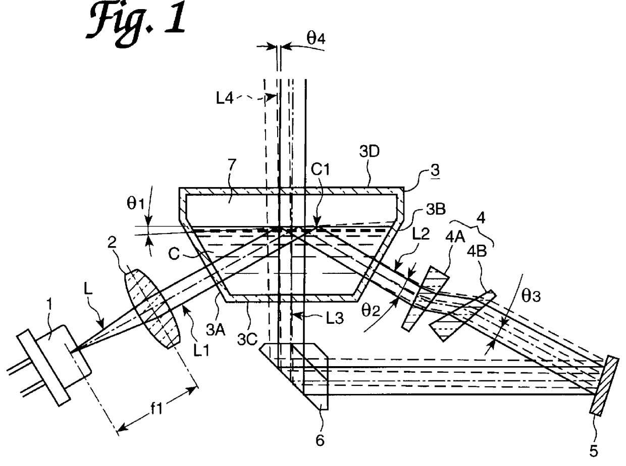
FIG. 1 shows the automatic inclination corrector according to the first embodiment of the invention. The automatic inclination corrector is built in various optical instruments (e.g., a laser beam emitting type measuring machine, or an optical leveler). The automatic inclination corrector comprises a laser diode 1, transparent container 3 for storing silicon oil C having a free liquid surface C1, a collimation lens (light projection system) 2 for guiding the laser beam L from the laser diode 1 to the free liquid surface C1, an anamorphic prism 4, a reflecting mirror 5, and a roof prism 6.

Laser diode 1 is arranged so that the laser beam L is emitted upward at an angle of 60 degrees relative to the horizontal line. Collimation lens 2 is positioned so that the focal point f1 of collimation lens 2 coincides with the position of the light source (laser diode 1). Laser beam L1 existing from the collimation lens 2 becomes collinated, and enters the free liquid surface C1 ...

second embodiment

(Second Embodiment)

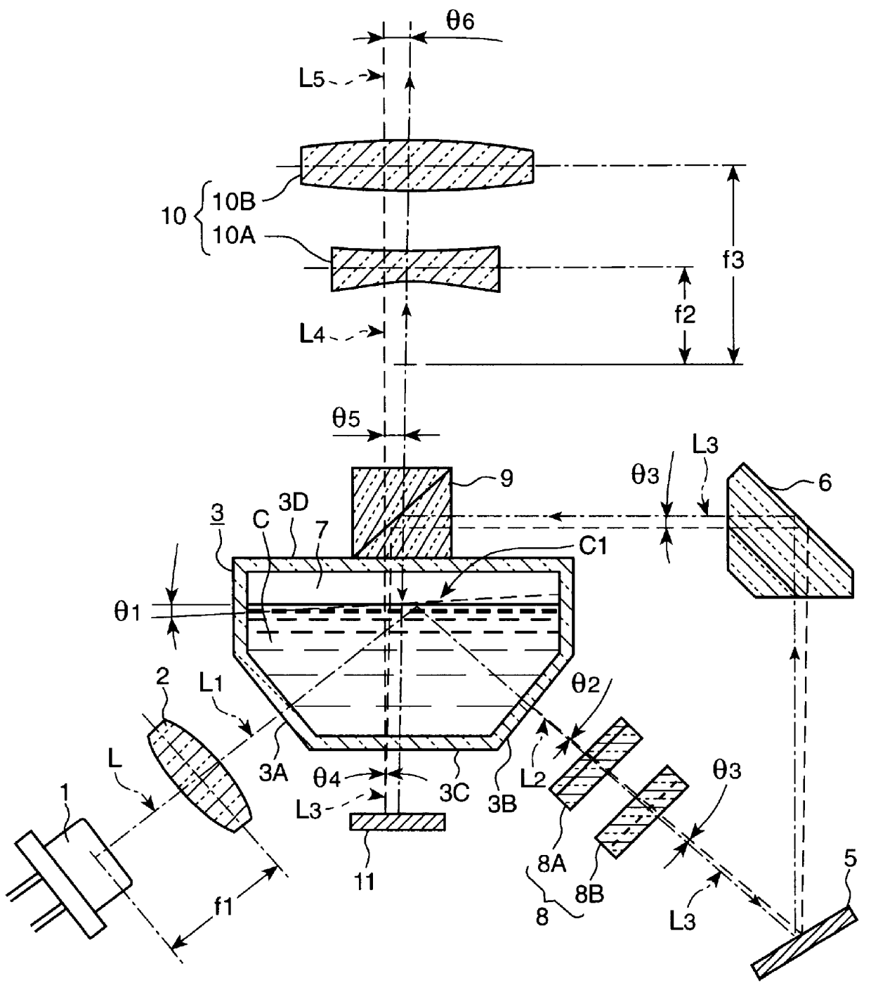
The automatic inclination corrector of the second embodiment will be described with reference to FIG. 3. In the automatic inclination corrector of the second embodiment, laser diode 1 is arranged so that the laser beam L is emitted upward at an angle of 45 degrees, and parallel, collinated light (laser beam L1) exits from the collimation lens 2 and enters the free liquid surface C1 at an incident angle of 45 degrees. The entry wall 3A of the transparent container 3 is perpendicular to the laser beam L1, and the exit wall 3B is perpendicular to the laser beam L2 which was totally reflected by the free liquid surface C1.

Galilean telescope 8 is positioned in the light path of the laser beam L2 which exits from the transparent container 3 after total reflection at the free liquid surface C1. The galilean telescope 8 is used to make the X and Y-axis components of the laser beam L2 equal, the laser beam L2 having exited through the transparent container 3 after total re...

third embodiment

(Third Embodiment)

The automatic inclination corrector of the third embodiment will be described with reference to FIG. 4. This automatic inclination corrector is a modification of that of the second embodiment.

Similar to the second embodiment, parallel light (laser beam L1) having passed through collimation lens 2 enters free liquid surface C1 with an incident angle of 45 degrees. Laser beam L3 having passed through Galilean telescope 8 is inverted by the roof prism 6, while being reflected in the horizontal direction. Half prism 9 is positioned in the light path of laser beam L3 reflected from the roof prism 6. The laser beam L3 from the roof prism 6 is again reflected by the half prism 9 vertically upward, enters the transparent container 3 through the bottom wall 3C, and passes through silicon oil C and the free liquid surface C1 from bottom to top. The inner surface 3D of the top wall 3D of transparent container 3 is a reflecting mirror surface 3D'. Laser beam L4, having passed ...


PUM


Abstract

An automatic inclination corrector and an inclination sensor using the automatic inclination corrector free from the temperature, for optical instruments. A transparent container 3 seals silicon oil C having a free liquid surface C1. A collimation lens 2 guides the laser beam from the diode 1 to the free liquid surface C1. The inclination corrector corrects the tilt of the instrument to glide the laser beam L4 from the container 3 to advance the beam upward with a normal angle. A reflecting mirror 5 reflects beam L2 after total reflection at the free liquid surface C1. The beam is inverted by a roof prism 6 and passes through silicon oil C and the free liquid surface C1 once. This removes the refractive index n influence to the laser beam L4, and gives an angular change to the laser beam 4 to head the laser beam L4 to a fixed direction.

Description

1. Field of the inventionThis invention relates to an automatic inclination corrector and an inclination sensor using the automatic inclination corrector. More particularly, this invention relates to an automatic corrector suitable to be used in a laser beam emission type measuring apparatus for construction, and an inclination sensor using such corrector.2. Related ArtFIG. 9 shows an example of prior art automatic inclination corrector, which is disclosed in Japanese Patent Application Laid-open H6-147891. The automatic inclination corrector comprises a laser diode 101, a transparent container 102 in which silicon oil C having a free liquid surface C1 is sealed, a collimation lens 103 for guiding the laser light L emitted from the laser diode 101 to the free liquid surface C1, a reflecting mirror 104, an anamorphic prism 105 positioned between the container 102 and the reflecting mirror 104, and a beam expander 106.The laser diode 101 emits laser beam L upward with an angle of 45 d...

Claims


Application Information

Patent Timeline
Patent Type & Authority Patents(United States)
IPC IPC(8): G01C15/00G01C15/10G02B27/64G01C5/02G01C9/06G01C9/20G12B5/00
CPCG01C15/002G02B27/648G01C15/105
Inventor KITAJIMA, EIICHI
Owner NIKON CORP
Why Eureka
Try Eureka