Linear optical scanner

a scanning device and optical scanner technology, applied in the field of optical scanning devices, can solve the problems of optical aberration, distortion and field curvature, optical system usually being substantially larger than the diameter of the scanned beam, and different optical aberrations

Inactive Publication Date: 2008-12-09
SHECHTERMAN MARK
View PDF13 Cites 5 Cited by
  • Summary
  • Abstract
  • Description
  • Claims
  • Application Information

AI Technical Summary

Problems solved by technology

Consequently there is substantial beam excursion across the system aperture, causing optical aberrations such as coma, distortion and field curvature.
Therefore, these optical systems usually are substantially larger than diameters of scanned beams and are complex in order reduce the different optical aberrations.
These optical systems typically require several aspherical surfaces (increasing cost) and provide at best no more than average resolution.
A second known disadvantage of the galvo-based scanners is the relatively large mass, especially for large beam diameters, and, consequently, large inertia of the oscillating system, which, especially with wide beams, strictly limits the scanning frequency.
Therefore, these optical systems usually are substantially larger than diameters of scanned beams, even more than galvanometric-based scanning systems, and complicated for purposes of different optical aberrations compensation (e.g. spherical aberration, coma, distortion, field curvature aberration).
Additional drawbacks of polygon-based scanning systems are low scanning efficiency and pupil's wandering, both due to polygon geometry.
Furthermore in order to separate the entrance and exit beams a relatively long optical path is required inside the Porro prism, hence a Porro prism does not support a large numerical aperture.

Method used


Image

  • Linear optical scanner
  • Linear optical scanner
  • Linear optical scanner

Examples


embodiment 130

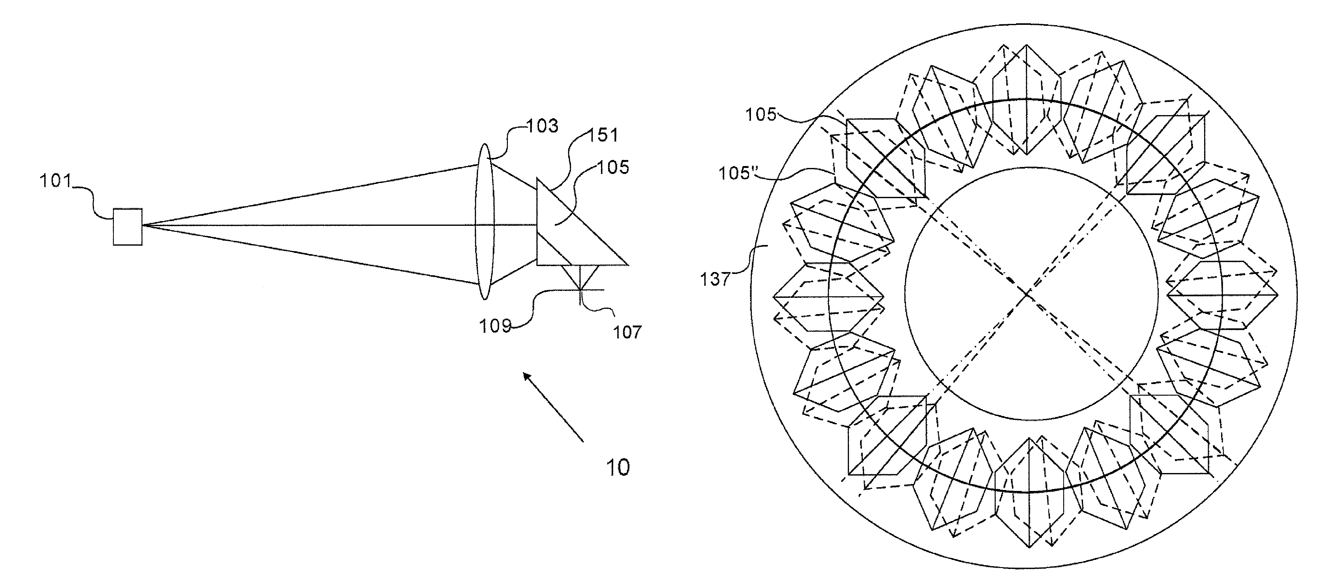
[0052]FIG. 10 presents circular arrangement of multiple Amici prisms in position 105, and another position 105″ on a rotating mechanical bearing disk 137 rotating about axis 123 as in embodiment 130. High rotating speed of such a disc with a large number of scanning Amici prisms, allows creating of enormous number of pixels, much more than can be supplied for instant by state of art polygon “mirrors.

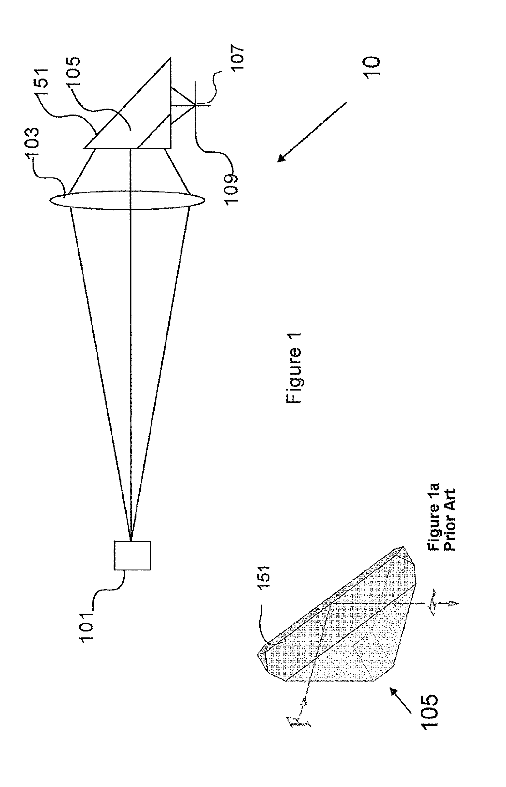
[0053]Reference is now made to FIG. 11, which illustrates an additional embodiment of the present invention. Point source 101 emits light rays which are imaged by imaging lens 103, through Amici roof prism 105, as scanning element. As presented in FIG. 11, a rotating scanning optical system is shown with Amici prism 105 rotating about axis 123 similar to embodiment 130. An additional optical relay lens 134, performs re-imaging of intermediate image at 109 into final image 109′. As is mentioned above, trajectory of intermediate image 109 could deviate from a straight line. Optical relay 1...

embodiment 80

[0054]An additional embodiment 80 of the present invention is illustrated in FIG. 12, of three-dimensional scanning in a transparent medium 147. Three lenses 141, 143 and 145 are used for re-imaging light emitted from illuminating source 101 through Amici roof prism 105, as scanning elements. Lens 143 (shown in two position 143 an 143′) is movable along the optical axis, creating a change in depth of focusing plane 149 or z-scan inside the transparent media. The optical system is optimized for compensation of spherical aberration caused by medium 147, at every depth of the focused beam 149 inside the transparent media 147, by pre-calculating of spherical aberration of the optical system at every corresponding axial position of lens 143. Lens 143 axial movement causes change of the focused beam position and scanning in depth is achieved as well as lateral scanning. Spherical aberration of the transparent medium 147 is strongly dependent on the depth of the focusing beam. Entire optic...


PUM


Abstract

A device for linear scanning includes a roof prism. The roof prism includes a roof of two mutually perpendicular reflecting surfaces intersecting in a line of intersection. A scanning mechanism moves the roof prism in a direction perpendicular to a plane of bilateral symmetry. The line of intersection is included in the plane of bilateral symmetry; and an incident beam entering the prism and an exit beam exiting the prism are angularly separated by a substantial angle. Preferably, the scanning mechanism generates periodic motion or rotational motion of the roof prism with a radius of motion greater than a dimension of the roof prism.

Description

FIELD AND BACKGROUND OF THE INVENTION[0001]The present invention relates to an optical scanning device; more particularly, to a device in which scanning is performed by reciprocating linear or continuous rotary movement of a ray-deflecting element.[0002]Optical scanning is well-known in which an image produced by an optical system is moved across an image plane typically including a photodetector. Optical scanning has many civilian as well as military uses. Present optical scanners include galvanometer-based devices. In the galvanometer based devices, the scanning movement is produced by a beam-deflecting element such as a flat mirror, which is angularly deflected, oscillating about an axis perpendicular to the optical axis by a galvanometer-type drive (e.g. moving-coil, moving-magnet drive). In these scanners, also known as galvo-based scanners, the oscillating mirror usually constitutes a pupil of the optical scanning system. Consequently there is substantial beam excursion across...

Claims


Application Information

Patent Timeline
Patent Type & Authority Patents(United States)
IPC IPC(8): G02B26/08G02B5/04
CPCG02B26/124
Inventor SHECHTERMAN, MARK
Owner SHECHTERMAN MARK
Why Eureka
Try Eureka