Sighting device with multifunction illuminated reticle structure

a technology of illuminated reticles and sighting devices, which is applied in the field of sighting devices with multi-function illuminated reticle structures to achieve the effect of being ready to produ

Active Publication Date: 2006-05-25
RAYTHEON CANADA LTD
View PDF10 Cites 6 Cited by
  • Summary
  • Abstract
  • Description
  • Claims
  • Application Information

AI Technical Summary

Benefits of technology

[0013] The present approach provides a rugged, readily produced sighting device for use with barrel-type weapons and in other applications. The user of the sighting device may selectively switch between two illuminated sighting reference features, such as a first set of sighting reference features useful in close-in situations and a second set of sighting reference features useful in longer-range situations.

Problems solved by technology

There is a need for such a sighting device, which is not currently available.

Method used


Image

  • Sighting device with multifunction illuminated reticle structure
  • Sighting device with multifunction illuminated reticle structure
  • Sighting device with multifunction illuminated reticle structure

Examples


Embodiment Construction

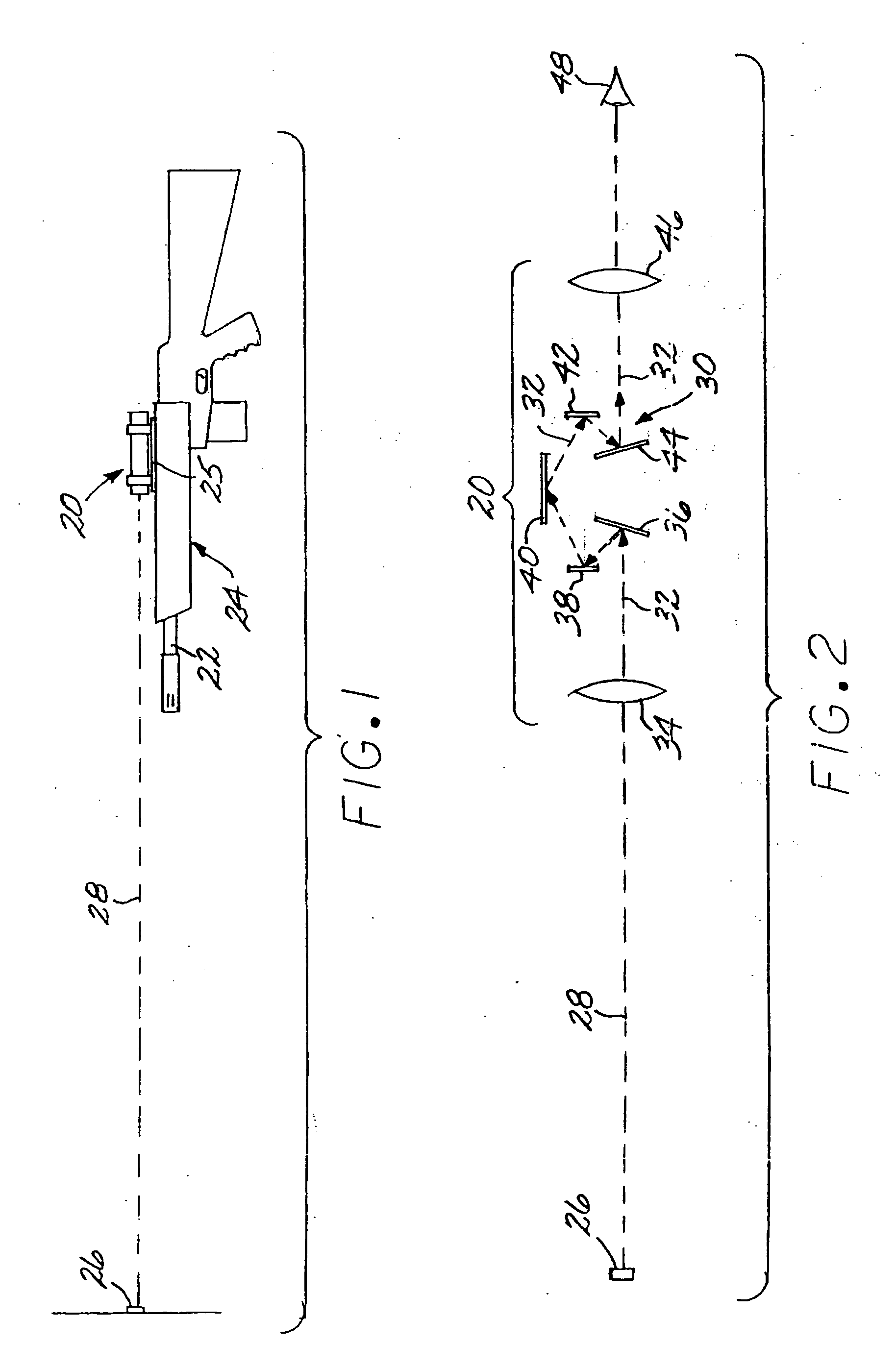
[0023]FIG. 1 depicts a sighting device 20 affixed to a barrel 22 (in this case through the barrel-support) of a rifle 24 with an adjustable mount 25 that allows the sighting device 20 to be moved relative to the barrel 22. The user of the rifle 24 aims the rifle 24 and the sighting device 20 at a distant target 26 along a line of sight 28. The sighting device 20, which typically includes telescopic optics, aids the user in aiming the rifle 24 at the target 26 of interest.

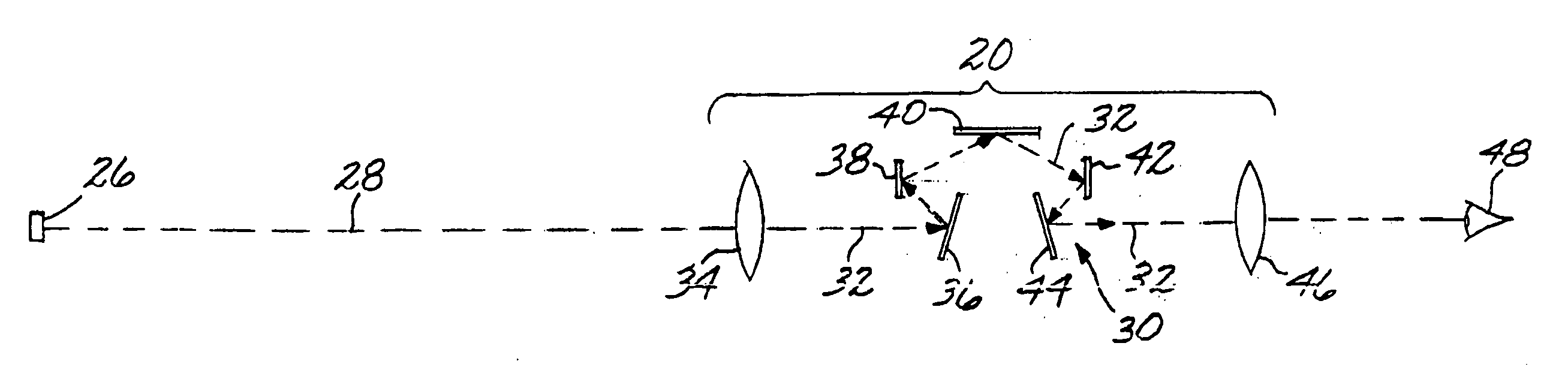
[0024]FIG. 2 illustrates a first embodiment of an optical layout of the sighting device 20. The sighting device 20 is affixed to the barrel 22 so that the line of sight 28 is aligned close to parallel to a bore of the barrel 22. However, the alignment is not perfect due to tolerances in the mechanical structure, changes in temperature, and the like. To achieve a more-precise alignment, the sighting device 20 is provided with a reticle structure 30. When the combination of the rifle 24 and the sighting device 20 is ...


PUM


Abstract

A sighting device is used to aim along a line of sight at a target. The sighting device includes a reticle structure formed of a roof prism assembly having an inclined final roof-prism mirror surface that is not perpendicular to the line of sight. The inclined final roof-prism mirror surface is the last surface of the roof prism assembly from which an optical path of the target reflects before leaving the roof prism assembly. There are two sets of sighting reference features, wherein the sets of sighting reference features are disposed on the inclined roof-prism mirror surface. A separately operable illumination source is provided for each of the sets of sighting reference features, wherein each illumination source illuminates only one set of sighting reference features.

Description

[0001] This invention relates to sighting and, more particularly, to a sighting device used to aim a weapon, aim an observation telescope, or in other applications. BACKGROUND OF THE INVENTION [0002] A hand-held weapon such as a rifle, pistol, or directed-energy device is aimed by pointing the barrel of the weapon at a target. To aid in the pointing, a sight is usually provided. “Iron” sights utilize fixed mechanical structure on the top of the barrel to aid in aligning the barrel toward the target. Laser sights project a laser beam that is placed on the target to aim the weapon. Telescopic sights use optics to view the image of the target, and typically enlarge the image of the target. The present approach is concerned with such telescopic sights. [0003] The telescopic sight includes a sighting reference feature such as a cross hair. The sighting reference feature allows the visual sighting by the user of the weapon to be brought into correspondence with the impact point of the pro...

Claims


Application Information

Patent Timeline
Patent Type & Authority Applications(United States)
IPC IPC(8): F41G1/00F41G1/01F41G1/38
CPCF41G1/01F41G1/38G02B23/02G02B27/34
Inventor BALL, ROGER WILLARD
Owner RAYTHEON CANADA LTD
Why Eureka
Try Eureka