RAID system having a selectable unattended mode of operation with conditional and hierarchical automatic re-configuration

a technology of automatic re-configuration and unattended mode, applied in the computer field, can solve the problems of data loss, lack of redundancy, and out-paced performance of newer processors and semiconductor memory technology, and achieve the effect of reducing the number of data loss

Inactive Publication Date: 2000-05-02
IBM CORP
View PDF10 Cites 120 Cited by
  • Summary
  • Abstract
  • Description
  • Claims
  • Application Information

AI Technical Summary

Problems solved by technology

Unfortunately, the performance of newer processor and semiconductor memory technology has out paced that of magnetic disk storage technology.
The primary disadvantage of RAID-0 is its lack of redundancy.
Consequently, any single disk failure in the array results in lost data.
RAID-1 is also error correcting because complete recover is possible from the failure of any one disk drive by simply switching to the drive that contains the duplicate copy of the data.
A disadvantage of RAID-1 is that it is expensive because it requires two times the number of drives necessary to stored the same data.
The necessity of making duplicate copies of all data also makes this RAID level somewhat slow to write data.
A primary disadvantage of this RAID level is that it only permits one request to be serviced at any one time.
A request to write data to a single stripe unit can be a relatively slow process, because it requires four disk accesses.
Requests for multiple writes to various stripe units located on different drives and in different stripes is even more problematic, because each write requires a read and write operation to the parity disk and, since there is only one parity disk, it can become "bottle necked."
A disadvantage of RAID-5, as well as RAID-3 and RAID-4, is its inability to correct a failure in more than one single disk.
As the size of disk arrays increases, however, the probability of a failure in more than one drive also increases which, in turn, increases the chance of an unrecoverable failure.
One disadvantage of RAID-6 over RAID-5, however, is in the write performance of small amounts of data on the order of one stripe unit in size.
For such small write operations, RAID-6 is even more inefficient because it requires a total of six accesses to update both the "P" and "Q" information.
Correct configuration data is essential to the operation of any array of independent disk drives, and loss of configuration data or inaccuracies in configuration data can be catastrophic.
For example, the RAID adapter itself may have been replaced due to its failure or for some other reason.
It is even possible to remove and replace the NVRAM or its battery power source from the adapter, thereby causing the loss of all configuration data in the NVRAM.
Other improper physical configuration errors may also occur, such as the insertion of a "foreign" disk drive into the host system, or the failure to replace one of the disk drives, thereby leaving an empty slot.

Method used


Image

  • RAID system having a selectable unattended mode of operation with conditional and hierarchical automatic re-configuration
  • RAID system having a selectable unattended mode of operation with conditional and hierarchical automatic re-configuration
  • RAID system having a selectable unattended mode of operation with conditional and hierarchical automatic re-configuration

Examples


Embodiment Construction

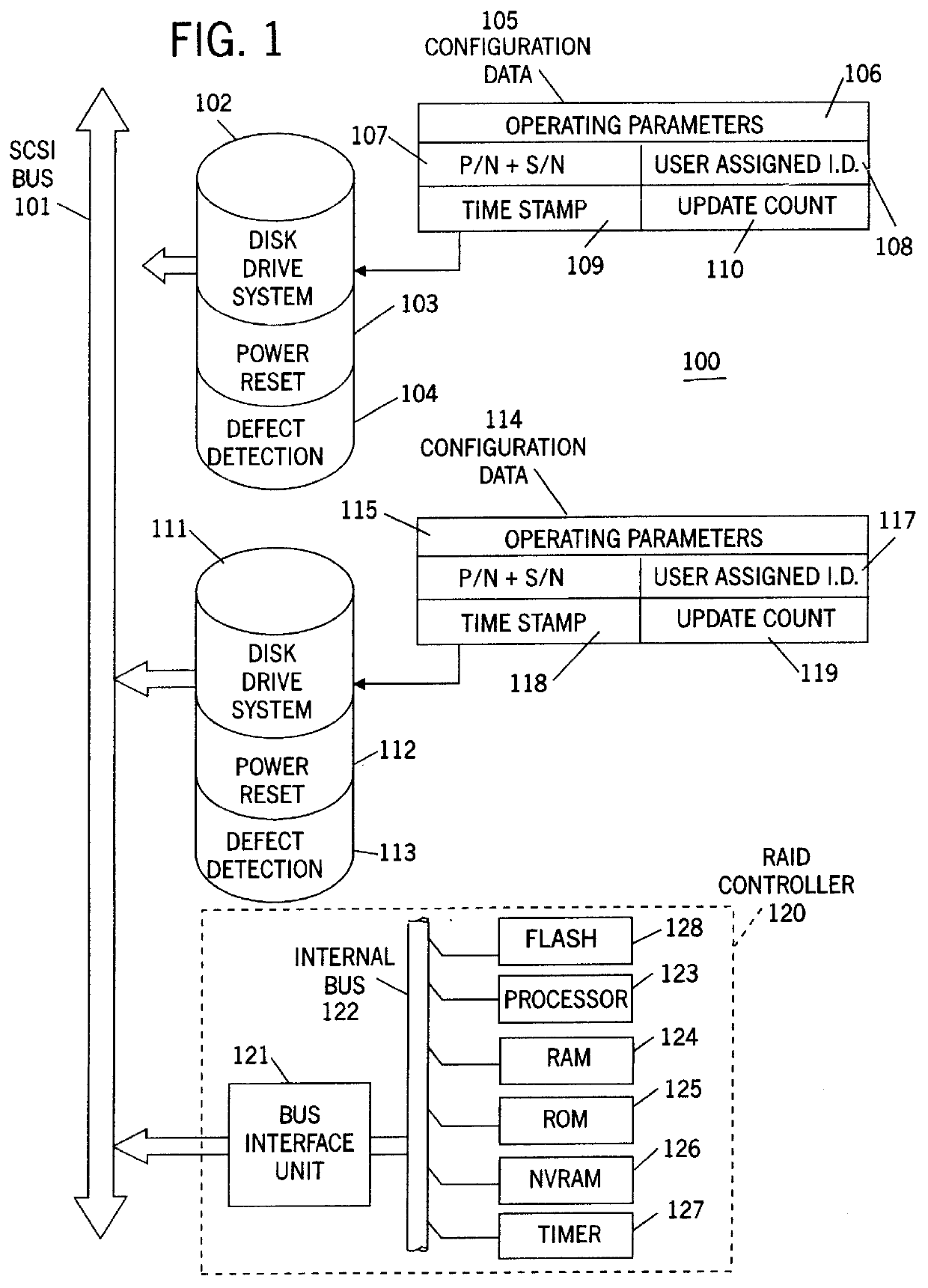
Table 1 is a code table that lists the configuration data that is stored in each of the disk drive units attached to the system, and is also stored in the RAID controller's NVRAM and flash memory.

Table 2 is a code table that lists the system management data that is stored in each of the disk drive units attached to the system, and is also stored in the RAID controller's NVRAM and flash memory.

Referring to FIG. 1, the RAID system 100 of the preferred embodiment includes a Small Computer System Interface ("SCSI") bus 101, although other bus architectures may also be used. A disk drive unit 102 can be connected to bus 101, but is illustrated in FIG. 1 as being disconnected from the bus. Disk drive unit 102 includes a well known power reset subsystem 103 that sends a signal out over bus 101 to indicate that a power reset has just occurred. For disk drive units that are designed to be attached to a SCSI bus, the signal that is sent out over the bus in response to a power reset is well kn...


PUM


Abstract

Because correct configuration data is essential to the operation of any RAID system, and because multiple copies of the configuration data are kept, not only in the RAID controller itself, but also in each disk drive unit in the configuration, it is imperative that the various copies of the configuration data do not become "out of synchronization", which means that one or more copies of the configuration data are different from one or more other copies of the configuration data. To maintain synchronization of all copies of the configuration data, the current invention compares the configuration data stored in the RAID controllers' NVRAM to that of the current system, and records any new, non-responding, repositioned or unidentified storage devices in a change list. The identities and the attachment points of any storage devices in the change list are then displayed to the user, and various options for correcting the lack of synchronization are provided by enabling one or more function keys that may be selected by the user. One such function key, an "accept change" key, causes the configuration data to be modified by changing the current operational state of any non-responding storage device. A "configuration adjustment" key, when selected by the user, causes the configuration data to be modified to reflect any changes in the attachments points of any repositioned storage deices. An "import configuration" key causes the configuration data to be changed to correspond to that of an unidentified storage device. And a "retry" key gives the user an opportunity to rearrange the system and then re-compares the configuration data in the controller to the current system configuration. When the system is operating in un-attended mode, means are disclosed to automatically perform the "accept change", "configuration adjustment" and "import configuration" functions in priority order so long as the "retry" key has not been enabled. The retry key implies attended operation.

Description

BACKGROUND OF THE INVENTIONThis invention pertains to computers and other information processing systems and, more particularly, to an information processing system that includes a redundant array of inexpensive disks ("RAID") with a means for synchronizing the disk configuration data.RAID OverviewAs the performance of microprocessor and semiconductor memory technology increases, there is a need for improved magnetic disk storage technology with comparable performance enhancements. Unfortunately, the performance of newer processor and semiconductor memory technology has out paced that of magnetic disk storage technology. In 1988, however, a paper published by Patterson, Gibson and Katz ("A Case For Redundant Arrays Of Inexpensive Disks (RAID)"; International Conference On Management Of Data; pp. 109-116; June 1988) laid the foundation for the use of a redundant array of inexpensive disks ("RAID") that would not only significantly improve the data transfer rate and data I / O rate over...

Claims


Application Information

Patent Timeline
Patent Type & Authority Patents(United States)
IPC IPC(8): G06F13/10G06F11/22G06F3/06
CPCG06F11/1096G06F13/10G06F11/2289G06F3/0601G06F2003/0697
Inventor ISLAM, SHAH MOHAMMAD REZAULOZA, BHARATKUMAR JAYANTILAL
Owner IBM CORP
Why Eureka
Try Eureka