Method and apparatus for sensing and displaying torsional vibration

a technology of rotating parts and torsional vibration, which is applied in the direction of instruments, surveying, and wellbore/well accessories, etc., can solve the problems of torsional vibration in the drill string, grinding of the drill string to a halt, and the stalling of the rotary tabl

Inactive Publication Date: 2000-05-23
HALLIBURTON ENERGY SERVICES INC
View PDF7 Cites 76 Cited by
  • Summary
  • Abstract
  • Description
  • Claims
  • Application Information

AI Technical Summary

Problems solved by technology

For example, variations in the torque applied to the drill string will result in a torsional vibration in the drill string.
At the outset of a stick-slip event, the rotation of the drill string grinds to a halt and the rotary table begins to stall due to the excessive buildup of torque in the drill string.
The buildup of torque causes the drill string to shorten, while the uncontrolled rotation tends to lengthen the drill string.
However, virtually all periodic variations in the torque applied to a drill string will cause uncontrolled accelerations of the various components making up the drill string, including the rotary table, bit, and BHA.
Like a stick-slip phenomena, these uncontrolled accelerations of the drill string may cause damage to the bit, any tools in the BHA, and may also cause wiping damage to the walls of the wellbore.
First, torsional vibrations introduce cyclic stresses that accompany the non-uniform rotational motion of the drill string.
Persistent twisting and unwinding of the drill string can lead to stalling of the drill string and overloading of connections, while fluctuating bit speed may cause fatigue failure of the cutting elements on the bit.
Second, bursts of lateral BHA vibration can accompany the rotational accelerations of the BHA.
These bursts can produce bending stresses that

Method used


Image

  • Method and apparatus for sensing and displaying torsional vibration
  • Method and apparatus for sensing and displaying torsional vibration
  • Method and apparatus for sensing and displaying torsional vibration

Examples


Embodiment Construction

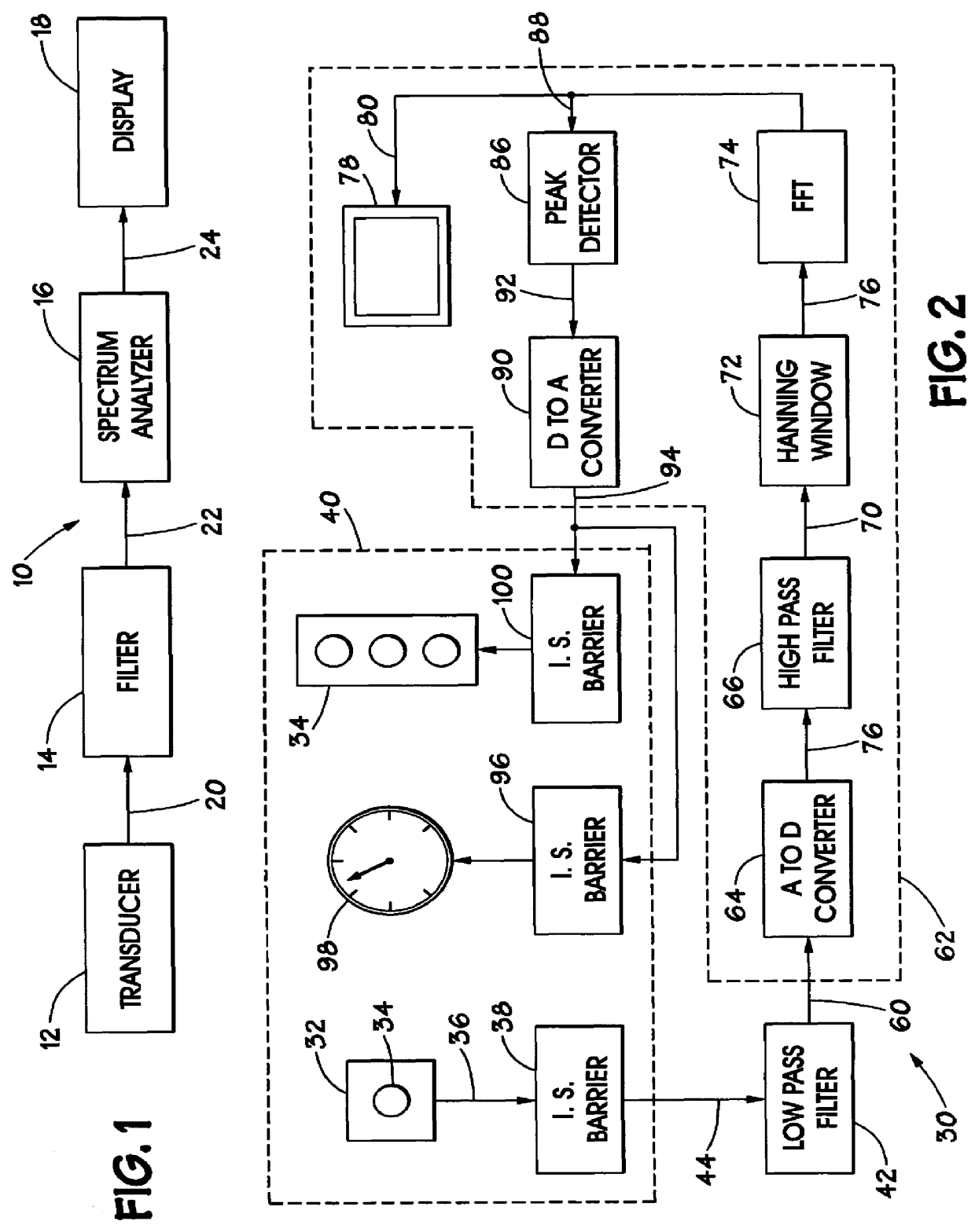
Turning now to the drawings and referring initially to FIG. 1, a method and apparatus for sensing and displaying torsional vibration is illustrated and generally designated by a reference numeral 10. The apparatus 10 includes a transducer 12, a filter 14, a spectrum analyzer 16, and a display 18.

Although the apparatus 10 may be used in various areas, it finds particular utility when used to sense and display torsional vibration experienced by a rotating member, such as a drill string (not shown). As is well known in the art, a drill bit is typically coupled to one end of a drill string, while the upper end of the drill string is coupled to a motor-driven rotary table on the drilling floor at the surface. The rotary table imparts a torque onto the drill string to rotate the bit at the opposite end of the drill string. However, as mentioned previously, other downhole events may occur and impart torque to the drill string.

The transducer 12 is provided to sense a parameter relative to t...


PUM


Abstract

A method and apparatus for sensing and displaying the magnitude of torsional vibrations. A transducer provides a signal indicative of the torsional vibrations being experienced by a rotating member. The magnitude of the frequency components of the signal are determined and displayed to an operator who may take corrective action.

Description

1. Field of the InventionThis invention relates generally to methods and apparatus for measuring the operating characteristics of a rotating member. More particularly, this invention relates to methods and apparatus for sensing and displaying torsional vibrations associated with a drill string.2. Description of the Related ArtDuring drilling operations, a drill string is subjected to axial, lateral, and torsional loads stemming from a variety of sources. In the context of a rotating drill string, torsional loads are imparted to the drill string by the rotary table, which rotates the drill string, and by the interference between the drill string and the wellbore. Axial loads act on the drill string as a result of the successive impacts of the drill bit on the cutting face, and as a result of irregular vertical feed rate of the drill string by the driller. The result of this multitude of forces applied to the drill string is a plurality of vibrations introduced into the drill string. ...

Claims


Application Information

Patent Timeline
IPC IPC(8): G01H1/10G01H1/00
CPCG01H1/10
Inventor DOMINICK, JOHN MCEWEN
Owner HALLIBURTON ENERGY SERVICES INC
Why Eureka
Try Eureka