

Vehicular pillar cover
- Summary
- Abstract
- Description
- Claims
- Application Information
AI Technical Summary
Benefits of technology
Problems solved by technology
Method used
Image

Examples
embodiment 1
(Embodiment 1)
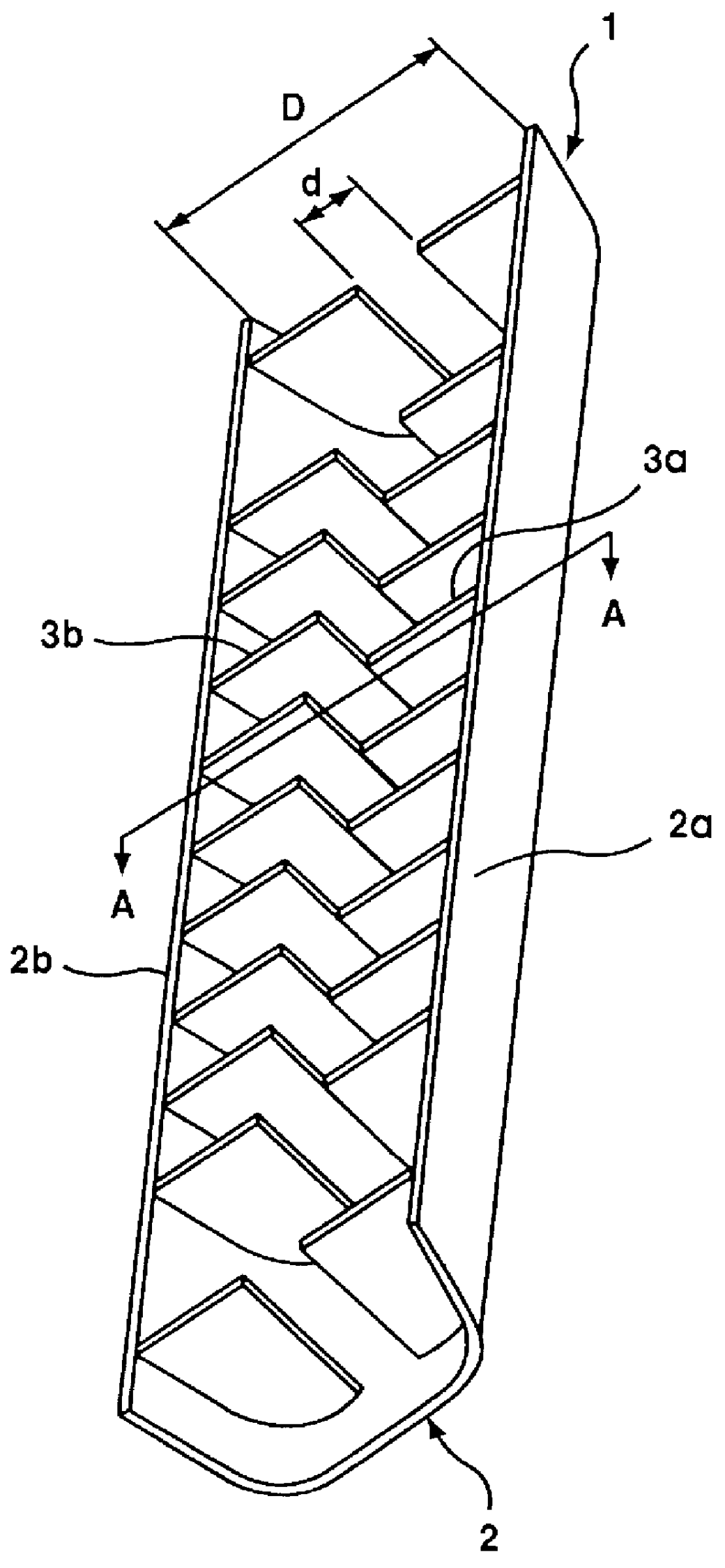
FIG. 1 is a perspective view showing a vehicular pillar cover according to Embodiment 1 of the invention.
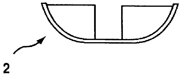
A vehicular pillar cover 1 is constructed to include a plurality of pairs of ribs 3a and 3b which are arranged in a body 2 having a generally C-shaped section, at a suitable spacing in the longitudinal direction of the body 2. The paired ribs 3a and 3b are extended generally at a right angle with respect to the longitudinal direction of the body from the individual side wall portions 2a and 2b of the body 2 toward the opposed side wall portions 2a and 2b. The ribs 3a and 3b are linearly opposed at their leading ends to each other through a gap d.
The vehicular pillar cover 1 may have a size suitably selected according to the size of the vehicle. Usually, the body 2 has a width of about 50 to 120 mm, a length of about 600 to 1,300 mm depending on the portion of the pillar and the size of the vehicle, a height of about 15 to 70 mm and a thickness of about 1.5 to 4.5 mm...
embodiment 2
(Embodiment 2)
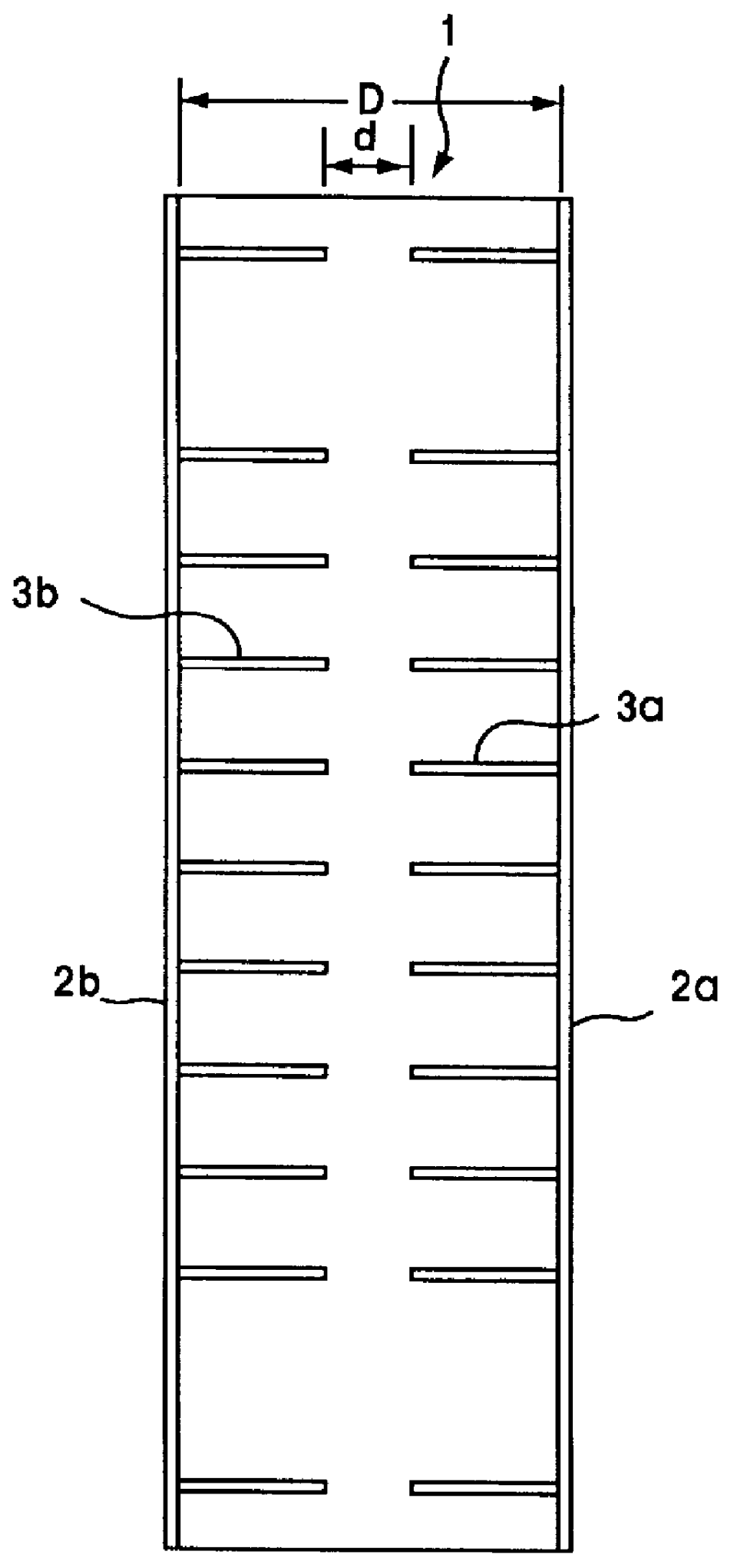
FIG. 2 is a perspective view showing a vehicular pillar cover according to Embodiment 2 of the invention.
A vehicular pillar cover 1 is constructed to include a plurality of pairs of ribs 3a and 3b which are staggered in a body 2 having a generally C-shaped section, at a suitable spacing in the longitudinal direction of the body 2. The paired ribs 3a and 3b are extended generally at a right angle with respect to the longitudinal direction of the body from the individual side wall portions 2a and 2b of the body 2 toward the opposed side wall portions 2a and 2b. The ribs 3a and 3b are opposed at their leading ends to the side wall portions 2a and 2b through a gap d.
The sections of the size of the vehicular pillar cover 1 and the size and (equally or differently distant, regular, irregular or random) array of the ribs 3a and 3b are similar to those of the foregoing Embodiment 1, and the gap d between the leading ends of the ribs 3a and 3b and the opposed side wall portions...
embodiment 3
(Embodiment 3)
FIG. 3 is a perspective view showing a vehicular pillar cover according to Embodiment 3 of the invention. The vehicular pillar cover 1 of Embodiment 2 (of FIG. 2) is modified such that the upper faces of the ribs 3a and 3b are removed to form cut-off portions 4a and 4b which are generally shaped to follow the inner side shape of the body 2. The remaining construction is similar to that of Embodiment 1.
With these cut-off portions 4a and 4b, as in this embodiment, the vehicular pillar cover 1 is assembled more compact by arranging a frame therein. Since the distance between the frame and the body 2 through the ribs 3a and 3b is constant, moreover, the impact damping ability is homogenized all over the surface of the vehicular pillar cover 1. The remaining effects are similar to those of Embodiment 2.
PUM
 Abstract
Description
Claims
Application Information