Impression system for an end of an implant projecting from a human tissue structure

a technology of human tissue and impression system, which is applied in the field of impression system with impression cap, can solve the problems of inaccuracy, difficult to achieve the effect of a master cast, and difficult to achieve the effect of assembling the elements in the patient's mouth,

Inactive Publication Date: 2000-05-30
STRAUMANN HLDG AG
View PDF1 Cites 145 Cited by
  • Summary
  • Abstract
  • Description
  • Claims
  • Application Information

AI Technical Summary

Benefits of technology

By virtue of the invention, an impression system with an impression cap is now available by means of which taking an impression of an implant end protruding from the tissue structure of a patient, with a possible superstructure, and the production of a master cast are greatly simplified. In addition, the transfer of the actual geometrical situation on the patient to the master cast is now more precise.

Problems solved by technology

On the one hand, the assembling of the elements in the patient's mouth, particularly in the area of the molars, is problematic because of the resulting overall height of the elements, especially if a screwing instrument has to be used as well.
Moreover, the work procedures are demanding for the patient, and they are time-consuming as regards impression-taking and production of the master cast.
In addition to this, inaccuracies occur.
The difficulties result primarily from the fact that the impression cap does not hold itself on the implant fitted in the mouth or on the manipulation implant to be used subsequently in the production of the master cast.

Method used


Image

  • Impression system for an end of an implant projecting from a human tissue structure
  • Impression system for an end of an implant projecting from a human tissue structure
  • Impression system for an end of an implant projecting from a human tissue structure

Examples


Embodiment Construction

A detailed description of illustrative embodiments of the impression system according to the invention is given hereinbelow with reference to the attached drawings, and possible modifications are discussed by way of conclusion.

The following statement applies to the whole of the description. If, for the purposes of clarity of the drawings, reference numbers are included in a figure but are not mentioned in the directly associated text of the description, then reference is made to their mention in preceding figure descriptions. In the interests of intelligibility, the repeated designation of components in succeeding figures is for the most part omitted, if it is clear from the drawings that the components concerned are "recurring" components.
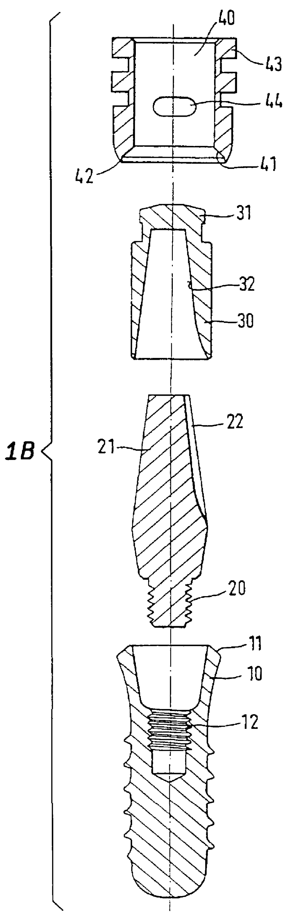
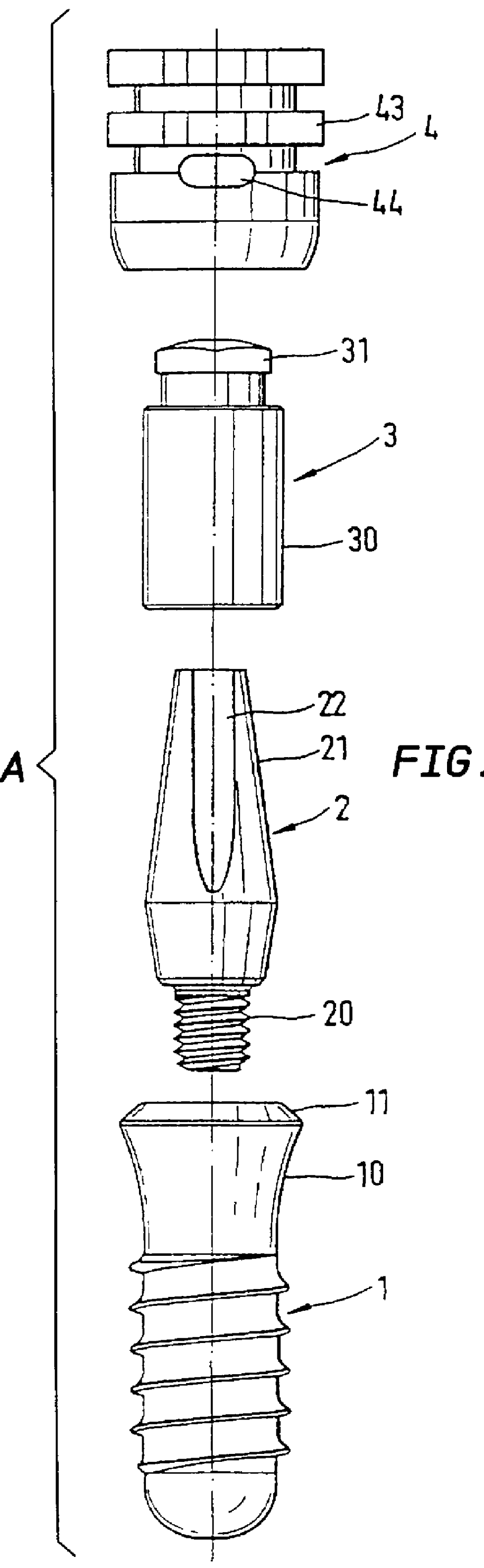
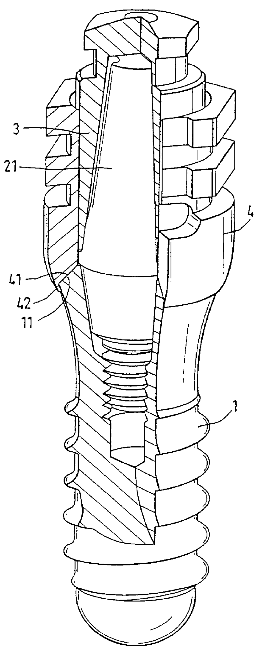
FIGS. 1A to 1G

Without wishing to limit the invention thereto, the example further refers to the taking of an impression of an implant 1 fitted in the mouth of a patient, here a dental implant as a full screw. The implant 1 has an implant head 10 w...


PUM


Abstract

PCT No. PCT/CH97/00031 Sec. 371 Date Apr. 28, 1998 Sec. 102(e) Date Apr. 28, 1998 PCT Filed Jan. 31, 1997 PCT Pub. No. WO97/28755 PCT Pub. Date Aug. 14, 1997An impression system includes an impression cap (4) for transferring an end, protruding from a human tissue structure, of an implant (1) which is fitted in the human body, including possible superstructures, to a master cast. The outwardly directed implant end has an undercut contour on its outside, and the impression cap (4) has a geometry which complements the undercut contour and engages therein. The undercut contour is formed either by an implant geometry tapering in a trumpet shape towards the implant bed, or by a recess near the implant end. Taking an impression and producing a master cast are greatly simplified with the impression system. In addition, the actual geometrical situation on the patient can be transferred to the master cast with greater precision.

Description

FIELDThe present invention relates to an impression system with an impression cap for an implant fitted in the human body in order to transfer the implant end protruding from the tissue structure, including possible superstructures on this implant end, to a master cast.PRIOR ARTThe following discussion refers in the first instance to the example of dental implants. For taking an impression of the situation in the patient's mouth and for transferring the impression obtained to a master cast, on which the tooth replacement is then modelled, a number of elements have hitherto been used. The work steps that have had to be performed to date, and the elements used in these work steps, are dealt with in detail by SCHROEDER, A.; SUTTER, F.; BUSER, D.; KREKELER, G.: Orale Implantologie [Oral implantology], Georg Thieme Verlag Stuttgart, 2nd edition, 1994, page 202 et seq. On the one hand, the assembling of the elements in the patient's mouth, particularly in the area of the molars, is proble...

Claims


Application Information

Patent Timeline
Patent Type & Authority Patents(United States)
IPC IPC(8): A61C8/00A61C9/00
CPCA61C8/0001A61C9/00
Inventor GRANDE, VINCENZOBAUMGARTNER, RETOTSCHIRKY, ROGER
Owner STRAUMANN HLDG AG
Why Eureka
Try Eureka