Suction control valve

a technology of suction control valve and valve body, which is applied in the direction of water supply installation, trachea tubes, medical devices, etc., can solve the problems of unacceptably low level of patient blood oxygen, difficult and expensive assembly of relatively many and expensive components, and difficulty in assembling large-scale components. , to achieve the effect of easy assembly and manufacturing design

Inactive Publication Date: 2000-06-06
SHERWOOD SERVICES AG
View PDF38 Cites 71 Cited by
  • Summary
  • Abstract
  • Description
  • Claims
  • Application Information

AI Technical Summary

Benefits of technology

A principal object of the present invention is to provide a fluid flow valving device which is designed to provide the user with an easily assemblable manufacturing design.
Another principal object of the present invention is to provide a fluid flow valving device which allows for complete and reliable gas sterilization thereof after its assembly.
An additional object of the present invention is to provide a fluid flow valving device which is easily actuatable by the operator regardless of the level of suction drawn therethrough by a suction source to which it may be attached.
A further object of the present invention is to provide a fluid flow valving device which is designed to allow attachment thereto of primary and ancillary devices such as a primary suction catheter device and an ancillary Yankauer suctioning device, which allows complete opening or closure of the primary device in isolation from the ancillary device, whereby the fluid flow valving device functions only as a connector of the ancillary device to the suction source and thus avoids any necessity of removing the fluid flow valving device from the suction source in order to attach the primary or ancillary device thereto, or to change from the use of one to the other.
An upper cap 17 is connected to the top portion of the valve body 13 and mates with the lower cap 14. A portion of a button 20 extends from the interior of the upper cap 17 through the upper cap opening 21 and above the annular surface 22. The positioning of the button 20 on the valve 10 is intended to allow for ease of manipulation thereof in a single hand of the user. The valve 10 is sized so as to be easily placeable within a user's palm such that the user's thumb may rest comfortably on the button 20, with the user's fingers curling about the lower cap 14 and cover 19.
Referring to FIGS. 3 and 13-14, a flexible, soft elastomeric spring 30 of generally cylindrical shape is positioned between the button 20 and the top of the valve body 13. The elastomeric spring 30 is held in its position by the seat 35 protruding from the top opening 33 of the conical bore 32. The spring 30 operates to hold the button 20 in its uppermost position where the button shoulder 31 abuts the upper cap 17. The spring 30 also operates to form an air tight seal between the upper extension 34 of the core 40 and the seat 35. The seal includes a sealing surface 44 against the upper extension 34 which allows relative vertical movement of the upper extension 34 therewith without loss of the air tight seal.

Problems solved by technology

Because of the necessary interruption in respiratory support to perform this procedure, a patient's blood oxygen often dropped to an unacceptably low level during suctioning, even when other previously known breathing assistance efforts were simultaneously provided.
The above and other prior art valving devices however suffer from several drawbacks, including but not limited to, being manufactured of relatively numerous and expensive components which are difficult and expensive to assemble, and being made to a design which does not allow for complete gas sterilization of the device after its assembly due to inaccessible and trapped regions therein which cannot be reliably penetrated by the sterilization gas.

Method used


Image

  • Suction control valve
  • Suction control valve
  • Suction control valve

Examples


Embodiment Construction

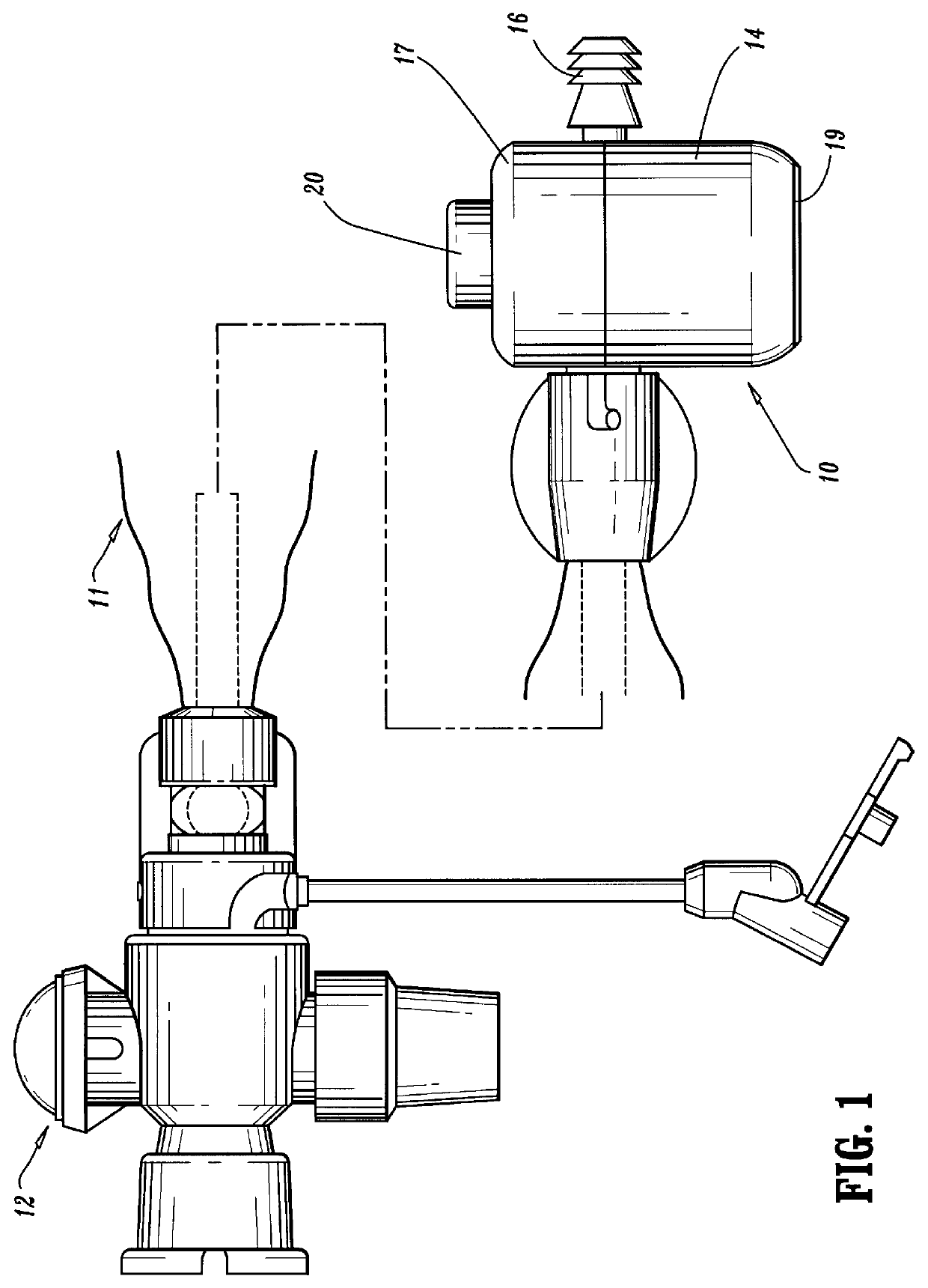
As shown in FIG. 1, preparation for operation of the valve 10 of the present invention includes attaching the primary device connector 15 thereof to the distal end of a primary device such as the suction catheter device 11, and attaching the suction source connector 16 to a suction tube 13 from a suction pressure source. When it is desired to administer suction to a patient, the suction catheter of the suction catheter device 11 is inserted through the manifold 12 into the patient's trachea or lungs, and the button 20 of the valve 10 is rotated to the "open" position as shown in FIG. 3.

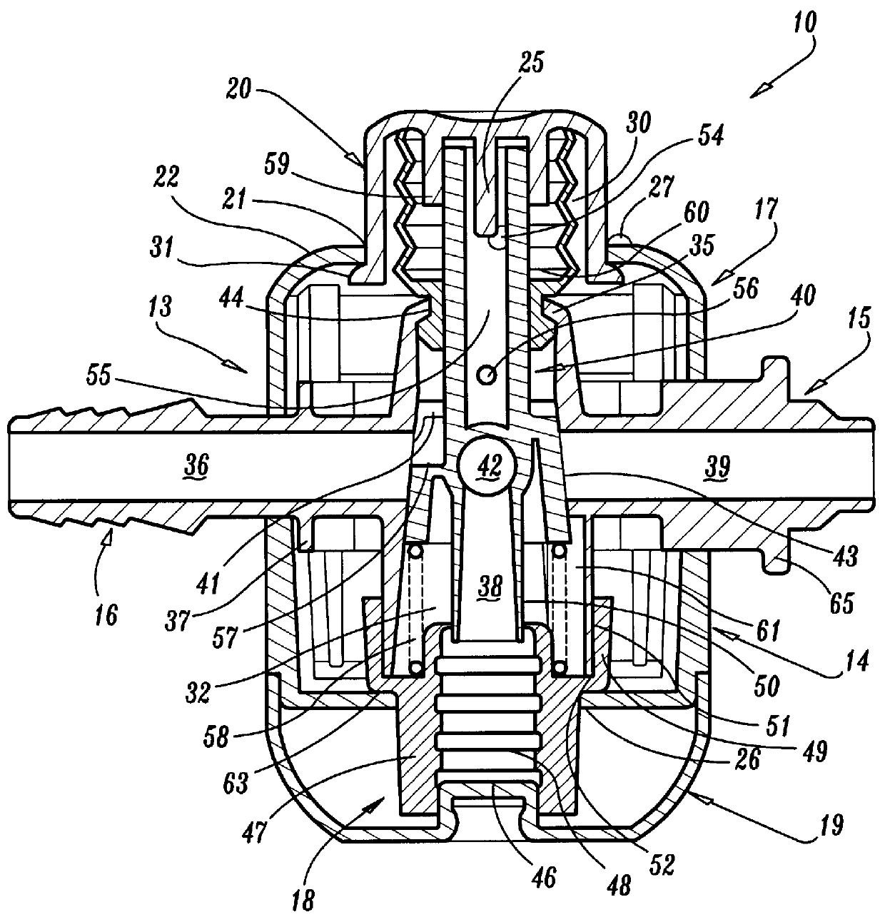
When in the open position, the valve 10 allows a bleed of suctioned atmospheric air to pass into the valve 10 through the upper cap opening 21 and move through the slot 53 of spring 30 (see FIG. 13) into the interior area of the spring 30. The air is then drawn through the bottom space 54 of slot 23 into a bleed by chamber 55 in the upper extension 34 of the core 40. From this position, the air passes...


PUM


Abstract

A suction control valve is disclosed which includes a primary suction device access and an ancillary suction device access. The valve includes a valve core which is linearly movable between a first position in which the primary access is closed against suction pressure therethrough, to a second position in which the primary access is open to suction pressure therethrough. The valve also is rotatable from the first position to a third position to disable its linear movement and to open the ancillary access port. When the core is in the first position, atmospheric air can pass through the valve and into the suction pressure source in such a manner that a "hissing" auditory signal is generated, indicative of the presence of suction pressure within the valve. When the actuator is in the second or third positions, the "hissing" is prevented. The valve is easily assembled and adapted for gas sterilization.

Description

1. Field of the InventionThis invention relates generally to fluid flow valving devices. More specifically, the present invention relates to a valve usable with a suction catheter. Even more specifically, the present invention relates to a suction control valve useable with suction catheters attachable to a respirator manifold of a respiratory system.2. Prior ArtRespiratory systems for ventilation of critically ill patients are now commonly used in medical facilities. The purpose of the respiratory system is to assist the patient in maintaining adequate blood oxygenation levels without overtaxing the patient's heart and lungs. Typically, a prior art respiratory system includes a tracheal tube positioned either directly or through the nose or mouth into the trachea of a patient. The tracheal tube is connected to a manifold at one port position thereof, and a source of breathable gas is connected at a second port thereof.While a patient is attached to a respiratory system, it is perio...

Claims


Application Information

Patent Timeline
Patent Type & Authority Patents(United States)
IPC IPC(8): A61M16/04A61M1/00
CPCA61M16/0463A61M1/0043A61M2205/6045A61M2205/43Y10T137/7058A61M1/7413
Inventor KEE, KOK-HIONG
Owner SHERWOOD SERVICES AG
Why Eureka
Try Eureka