Modular load unit for muzzle loading firearms

a module-type, firearm-type technology, applied in the direction of weapons, muzzle-loading small arms, small arms, etc., can solve the problems of not being able to load a muzzle-loader exactly the same every time, not being able to use a muzzle-loader as simple, etc., to reduce friction, eliminate projectile deformation upon ignition, and load a muzzle-loading firearm

Inactive Publication Date: 2000-07-11
CAUDLE CARL E
View PDF4 Cites 30 Cited by
  • Summary
  • Abstract
  • Description
  • Claims
  • Application Information

AI Technical Summary

Benefits of technology

Another advantage of the present invention is to provide a device that can be used in all models of muzzleloaders.
Still another advantage of the present invention is to provide a method of loading a muzzleloader at any angle.
Another advantage of the present invention is to provide a device and method for loading a muzzleloader that eliminates projectile deformation upon ignition.
Another advantage ...

Problems solved by technology

Returning to a simpler way of life is one of the lures of muzzleloading; however, using a muzzleloader is not as simple as it could be.
The distance and accuracy of each shot fired from a muzzleloader is dependent upon the way the gun is loaded, and yet it is nearly impossible, with current methods, to load a muzzleloader exactly the same every time.
Steady, even pressure is required to avoid deforming the ball, which can lead to poor ballistic performance and inaccurate shooting.
The problems associated with loading a muzzleloader include the following: 1) each load is put down the bore by hand, relying on gravity to position the load properly; 2) sloppy or inconsistent loading practices increase the risk of dangerous accidents; 3) sloppy or inconsistent loading practices decrease shooting accuracy; 4) the components of each load, which must be held outside the gun at least brief...

Method used


Image

  • Modular load unit for muzzle loading firearms
  • Modular load unit for muzzle loading firearms
  • Modular load unit for muzzle loading firearms

Examples


Embodiment Construction

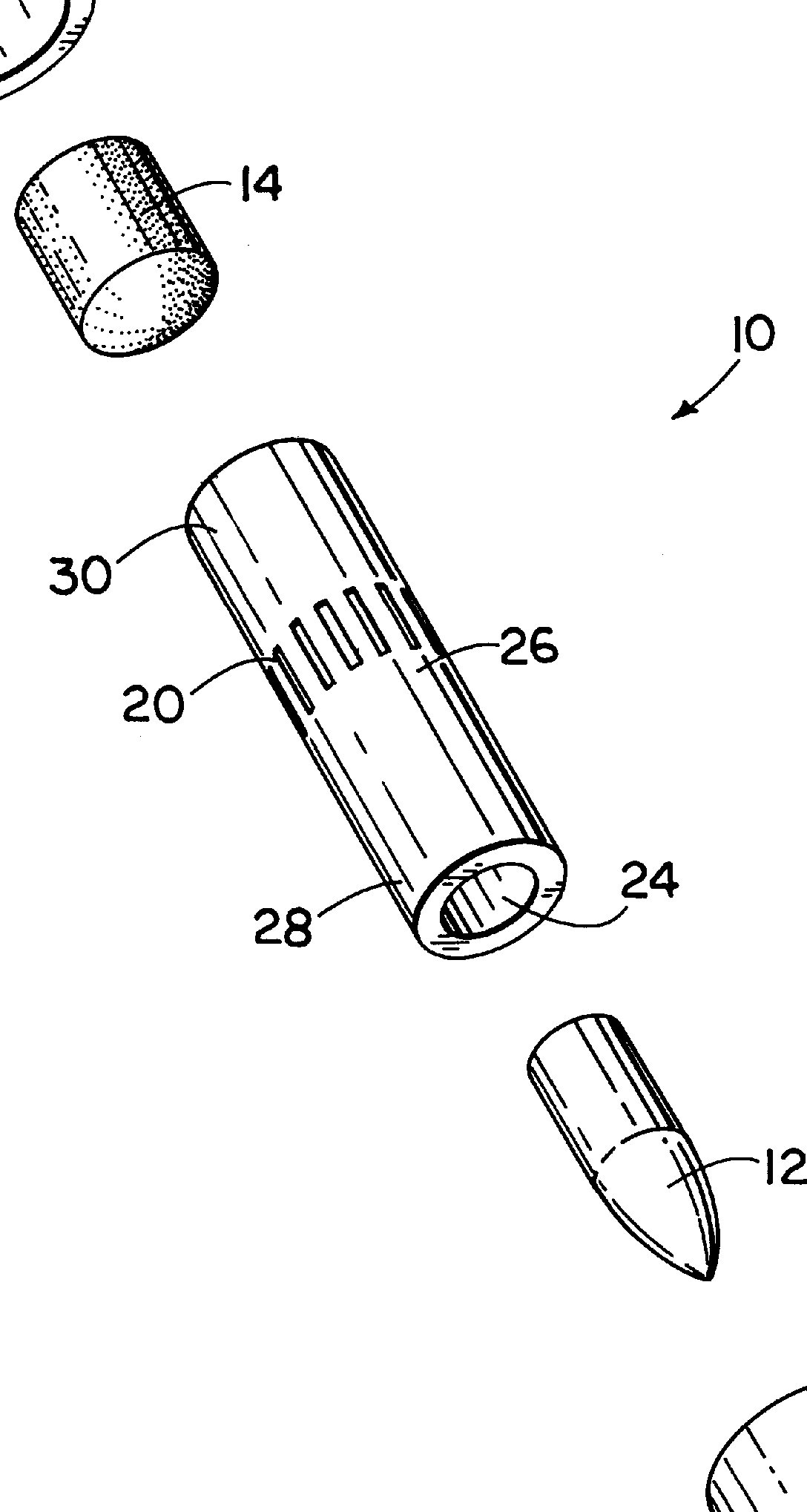
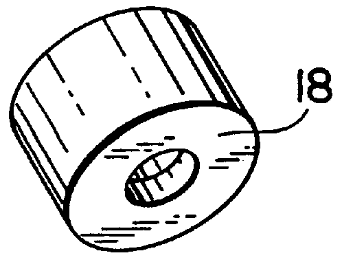
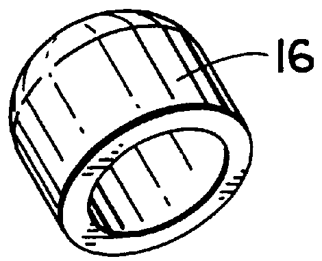
With reference to FIGS. 1-10 and 14-24, a modular load unit 10 is shown, the modular load unit comprising a hull body 26, a projectile receiving compartment 24, a propellant receiving compartment 22, and a cushion 20. The modular load unit is received in a muzzle loading firearm (not shown), which includes a barrel 32 with a bore 44 having rifling grooves 34, as shown in FIGS. 19-22. With reference to FIG. 22, the bore has a breech plug 38. The breech plug is a threaded plug, typically made out if metal, which is screwed into the breech (not shown) as a seal at the rear of the bore where the charge is held. The bore has a bore diameter. The rifling grooves have a rifling diameter which is greater than the bore diameter. The hull body of the modular load unit has a diameter which is substantially the same as the bore diameter of the barrel.

With reference to FIG.1, the hull body 26 of the modular load unit 10 is elongated and cylindrical and has a first end 28 and a second end 30. The...


PUM


Abstract

A modular load unit that is received in a muzzle loading firearm having a bore and a rifling defined therein. The modular load unit has a hull, a projectile in a projectile receiving compartment, a projectile retaining cap removably received over the projectile, a cushion, a propellant in a propellant receiving compartment, and a propellant retaining cap removably received over the propellant. The modular load unit can be inserted into the bore of the muzzle loading firearm at any angle. Upon firing of the muzzle loading firearm, the cushion and the propellant receiving compartment sealingly engage the rifling.

Description

The present invention relates to the field of firearms. More particularly, the invention pertains to a modular unit and method for loading a muzzleloader which ensures improved ballistic performance, safety, accuracy, and convenience; allows faster reloading; allows self-cleaning; increases weather-resistance; and eliminates the traditional gravity feed operation and the possibility of projectile deformation.The class of firearms known as muzzleloader is old and well known. Shooting muzzleloading guns of all types has become a pastime of considerable and growing importance. Returning to a simpler way of life is one of the lures of muzzleloading; however, using a muzzleloader is not as simple as it could be. The muzzleloader is characterized by the method of loading where a propellant charge and a projectile are each individually loaded through the bore and into the chamber of the barrel through a gravity feed operation. In this class of firearms, a separate source of ignition is pro...

Claims


Application Information

Patent Timeline
IPC IPC(8): F42B5/00F42B5/10F42B14/06F41C9/00F41C9/08F42B14/00
CPCF41C9/085F42B5/105F42B14/06
Inventor CAUDLE, CARL E.
Owner CAUDLE CARL E
Why Eureka
Try Eureka