Direct chip-cooling through liquid vaporization heat exchange

a heat exchange and liquid vaporization technology, applied in the direction of insulated conductors, semiconductor/solid-state device details, cables, etc., can solve the problems of thermal management, the burden of cooling has been shifting from the system level to the component level, and the apparatus of this reference is considerably limited by the internal resistance between the components

Inactive Publication Date: 2000-07-11
IBM CORP
View PDF19 Cites 118 Cited by
  • Summary
  • Abstract
  • Description
  • Claims
  • Application Information

AI Technical Summary

Benefits of technology

The present invention is directed to, in yet another aspect, an improved electronic module having a chip and substrate mechanically and electrically interconnected wherein the improvement comprises a metal wick disposed on the chip; and a heat sink enclosure sealably attached to the chip and the wick having a plurality of cooling fins therein sufficiently filled with a working liquid to constantly wet the wick, such that heat generated by the chip is adapted to be transferred to the metal wick, vaporizing the liquid to condense on the cooling fins while the heat sink enclosure absorbs the heat carried by the vapors of the liquid and conducts the heat to an outside surface of the heat sink enclosure. The heat sink enclosure of the improved electronic module may further comprise a plurality of cooling fins on an exterior surface of the heat sink enclosure.

Problems solved by technology

Thermal management is a key issue in the design of the electronic package.
In the case of high performance machines, the burden of cooling has been shifting from the system level to the component level.
However, the apparatus of this reference is considerably limited by the internal resistance between the component and the heat-sinking closure since the heat must flow from a chip through the substrate, heat sink, and wick in order to vaporize the working fluid within the heat sink enclosure.
However, there is a great deal of thermal resistance across package layers, interconnects, and interfaces from the chip or component to the substrate, which limits the rate at which the heat can be dissipated despite the efficiency of the heat pipe mechanism.
Due to the internal resistance through many interfaces and the long piping system, the cooling process is not as efficient.
Again as in other prior art cooling mechanisms using heat pipes, the limitation of multiple resistances along the heat path limit the heat removal efficiency.
The battery of thermal resistances severely limit the heat dissipation rate.

Method used


Image

  • Direct chip-cooling through liquid vaporization heat exchange
  • Direct chip-cooling through liquid vaporization heat exchange

Examples


Embodiment Construction

)

In describing the preferred embodiment of the present invention, reference will be made herein to FIGS. 1-2 of the drawings in which like numerals refer to like features of the invention. Features of the invention are not necessarily shown to scale in the drawings.

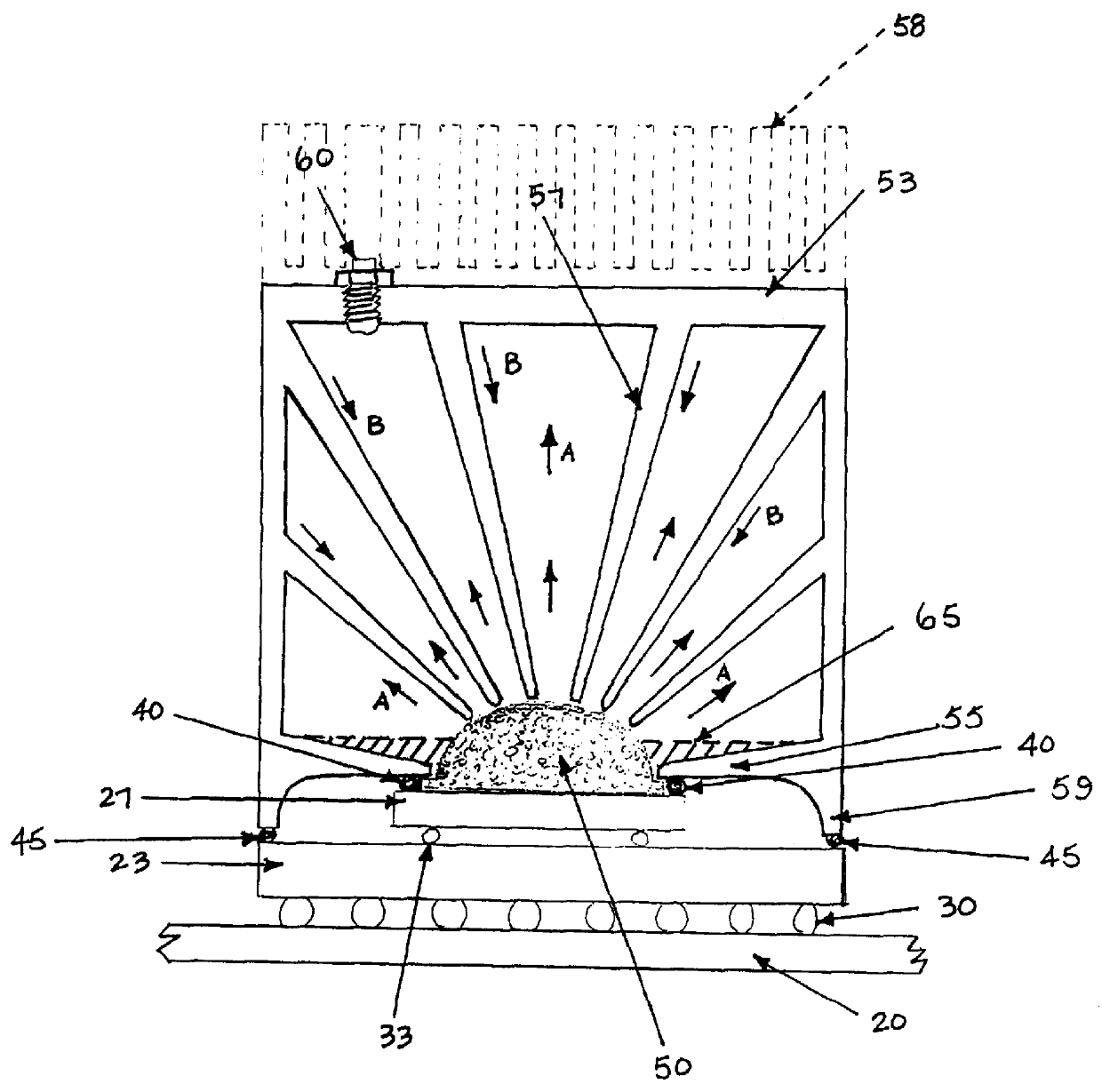
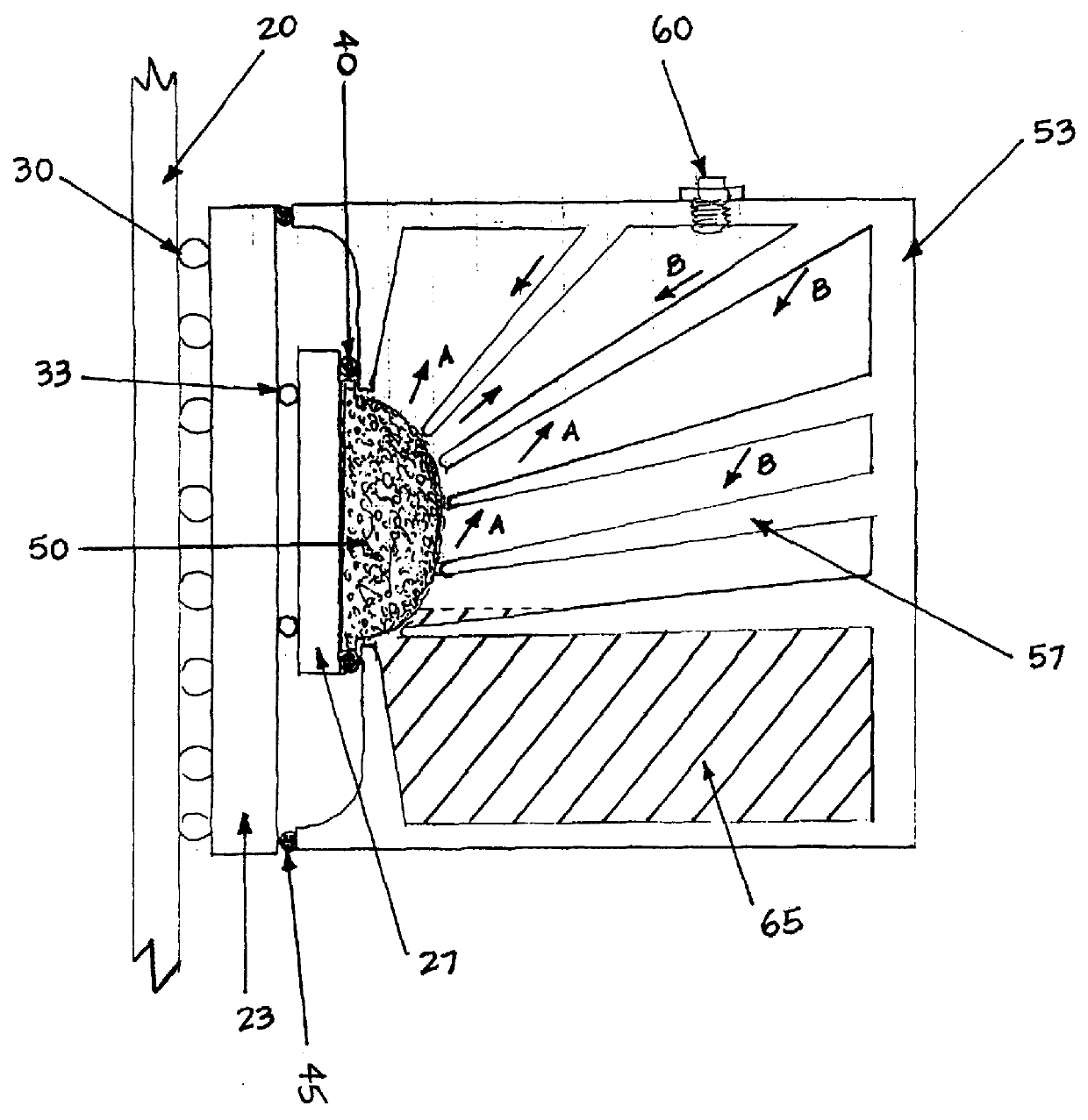
In FIGS. 1 and 2, there is shown an electronic package being cooled with a preferred embodiment of the present invention. The electronic package comprises of a card or circuit board 20 wherein substrate 23 is mounted to the card 20 and is physically and electrically connected utilizing, for example, a ball grid array 30. The ball grid array 30 comprises a number of solder balls which electrically and physically connect the substrate to the printed circuit board. Mounted on substrate 23 is semiconductor chip 27. Chip 27 is electrically and physically connected to substrate 23 by solder interconnections 33. During operation of the electronic device or module, heat dissipation rates of about 20 to 100 Watts are needed depend...


PUM


Abstract

An apparatus for and method of cooling an electronic module comprising a heat sink enclosure placed directly over a chip or substrate in a flip chip package. The heat sink enclosure has a plurality of cooling fins extending from within the cavity of the enclosure. A liquid sealed inside the enclosure is trapped within a thermal transfer means, preferably a metal wick, which sits directly on a chip or substrate. As the chip or substrate heats up, heat is transferred to the thermal transfer means which in turn heats the liquid to its heat of vaporization. The vapors of the liquid rise and condense on the cooling fins and the heat is absorbed by the enclosure and conducted to an outside surface of the enclosure and dissipated. Cooling fins on an exterior surface of the enclosure further reduces the thermal resistance to enhance cooling.

Description

1. Field of the InventionThe present invention relates to the design and manufacture of semiconductor devices, in particular, a method of and apparatus for cooling a semiconductor chip in an electronic package.2. Description of Related ArtThermal management is a key issue in the design of the electronic package. The proper design insures that the peak temperatures remain within a specified operating range to produce a reliable module. The main objective is to maintain the semiconductor device junction temperature below the maximum operating temperature of the module. Design challenges included in heat removal are higher circuit densities, close proximity of adjacent devices or components, low thermal conductivity substrates, inner layers of metal forming the interconnect, and the thermal resistance of heat sink systems.The purpose of any heat transfer design is to allow the flow of thermal energy from heat source to heat sink within the constraints of specified temperature levels. I...

Claims


Application Information

Patent Timeline
Patent Type & Authority Patents(United States)
IPC IPC(8): F28D15/02F28D15/04H01L23/34H01L23/427
CPCF28D15/0233F28D15/046H01L23/427H01L2924/0002H01L2924/00
Inventor DIGIACOMO, GIULIOIRUVANTI, SUSHUMNAWOMAC, DAVID J.
Owner IBM CORP
Why Eureka
Try Eureka