Detector for sensing motion and direction of a railway device

a technology of motion and direction detection and detector, which is applied in the direction of generators/motors, instruments, transportation and packaging, etc., can solve the problems of difficult for the engineer or other operator to reliably be informed of the state of motion of one or more vehicles, difficult for the train driver to know, and difficult for the driver to know when the last car has been decelerated to a standstill

Inactive Publication Date: 2000-07-11
THE UNION SWITCH & SIGNAL
View PDF11 Cites 124 Cited by
  • Summary
  • Abstract
  • Description
  • Claims
  • Application Information

AI Technical Summary

Problems solved by technology

In railway systems such as those employing locomotive drawn trains, it can sometimes be difficult for the engineer or other operator to reliably be apprised of the state of motion of one or more vehicles that are located remotely from him.
For example, when starting a train from a stop position it can in some operations be particularly difficult for the train driver to know when the driving force of the locomotive has propagated through the interconnected cars and accelerated the last vehicle into motion.
Conversely, when coming to a stop, it is difficult for the driver to know when the last car has been decelerated to a standstill.
In addition, some older types of sensors do not report directio

Method used


Image

  • Detector for sensing motion and direction of a railway device
  • Detector for sensing motion and direction of a railway device
  • Detector for sensing motion and direction of a railway device

Examples


Embodiment Construction

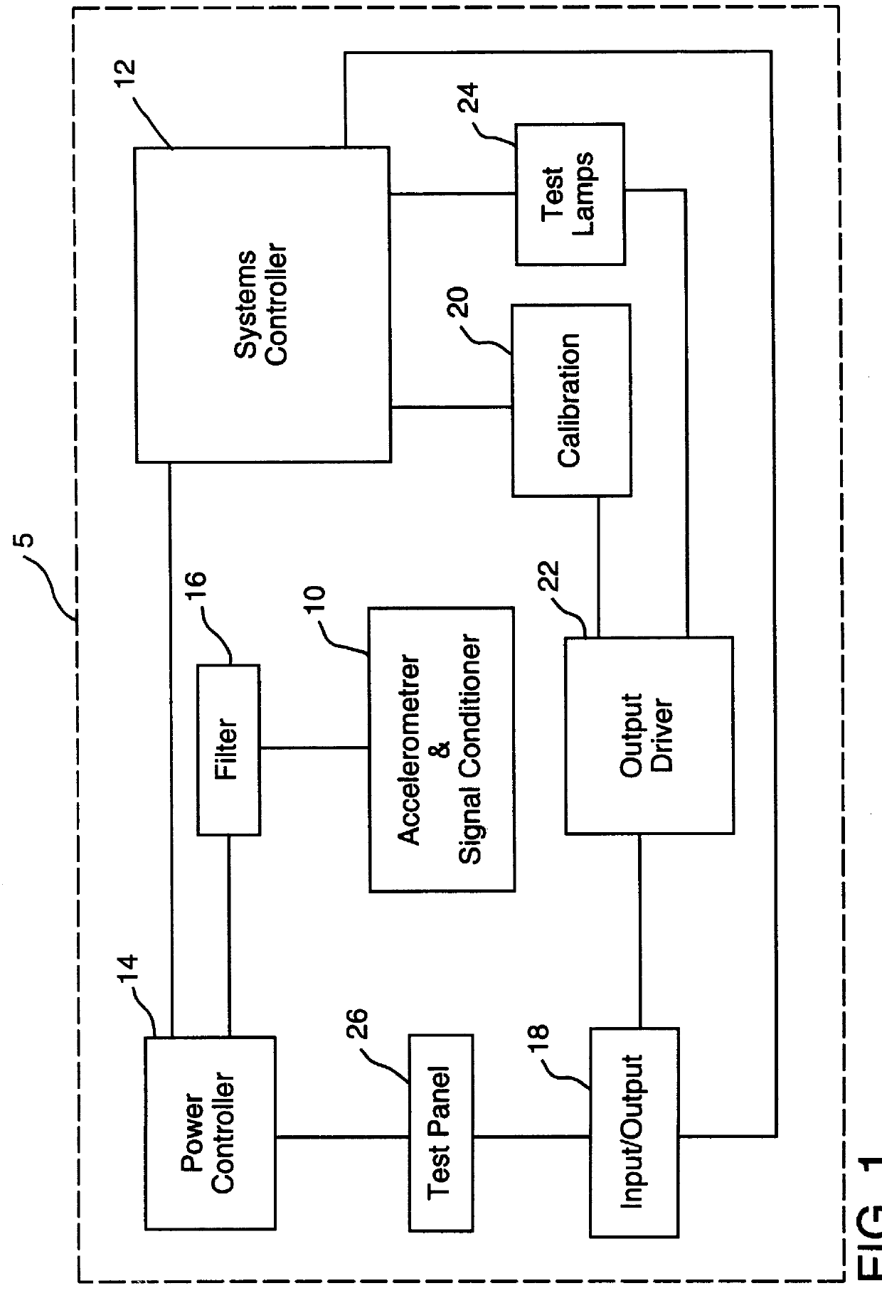
Referring now to the drawing figures wherein like reference numbers refer to similar parts throughout the several views, and particularly to FIG. 1, there is shown in block diagram form certain components of a motion detector 5 having features of the present invention.

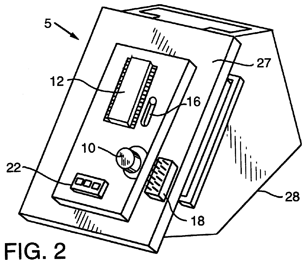
The motion detector 5 can include an accelerometer 10 for generating signals corresponding to acceleration. A systems controller 12, which can include an analyzer, can be provided to receive and analyze the signals from the accelerometer 10 and to control the overall operation of the motion detector 5. The motion detector 5 can also have a power controller 14, a filter 16, an input / output port 18, a calibration unit 20, an output driver 22, test lamps 24, and a test panel 26.

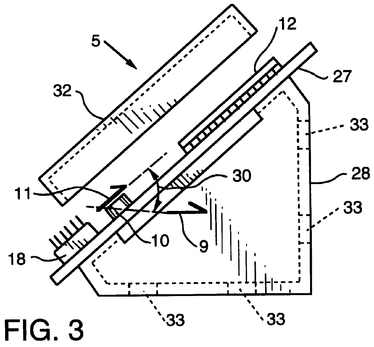
The single axis accelerometer 10 can be mounted at an angle from a plane formed by the rails, as indicated by reference number 30 in FIG. 3. The accelerometer 10 can preferably be positioned such that the axis of sensitivity, represented by vector ...


PUM


Abstract

A motion detector for detecting movement of a rail based vehicle and the direction of that movement is provided. The motion detector can be integral with or attachable to an end-of-train unit and can include a single axis accelerometer mounted at an angle from the rails for detecting acceleration in both the lateral and vertical directions. A systems controller, which can include an analyzer, can be provided to receive and analyze output from the accelerometer to determine a motion state and a direction. A power controller can be provided for supplying power to the accelerometer on an intermittent basis to conserve power. A calibration unit can be provided to both initially calibrate and to subsequently recalibrate the accelerometer after a stopped motion state is detected. Additionally, an input/output port and an output driver for conditioning the signal for output to the end-of-train unit can be provided.

Description

1. Field of the InventionThe invention relates generally to motion detectors, and more particularly to a motion and direction detector of a railway vehicle and in some applications on an end-of-train (EOT) railroad telemetry system.2. Description of the Prior ArtIn railway systems such as those employing locomotive drawn trains, it can sometimes be difficult for the engineer or other operator to reliably be apprised of the state of motion of one or more vehicles that are located remotely from him. For example, when starting a train from a stop position it can in some operations be particularly difficult for the train driver to know when the driving force of the locomotive has propagated through the interconnected cars and accelerated the last vehicle into motion. Conversely, when coming to a stop, it is difficult for the driver to know when the last car has been decelerated to a standstill. Knowledge of these conditions of motion of the last vehicle can be extremely useful to the dr...

Claims


Application Information

Patent Timeline
IPC IPC(8): B61L1/14B61L15/00B61L1/00B61L25/02
CPCB61L1/14B61L15/0036B61L15/0054B61L15/0081B61L25/023
Inventor CAPAN, RONALD R.
Owner THE UNION SWITCH & SIGNAL
Why Eureka
Try Eureka