Stent loading assembly for a self-expanding stent

a self-expanding, stent technology, applied in the field of stent loading assembly, can solve the problems of self-expanding stents (both radioactive), reclosure or restnosis of the vessel, and the inability to perform proper compression of self-expanding stents, and achieve the effect of restraint, and reducing the risk of resection

Inactive Publication Date: 2000-07-18
ISOSTENT
View PDF14 Cites 90 Cited by
  • Summary
  • Abstract
  • Description
  • Claims
  • Application Information

AI Technical Summary

Problems solved by technology

Problems occur, however, when the dilatation of the occlusion forms fissures, flaps and/or dissections which may ultimately cause reclosure or restenosis of the vessel.
The primary problem associated with these deployment devices, however, is that the self-expanding stents (both radioactive and non-radioactive stents) must be compressed before being installed in the distal tube of the deployment device.
The proper compression technique for a self-expanding stent, however, is extremely difficult to perform, and is generally acquired only through substantial practice and experience.
A variety of subjective conditions, such as

Method used


Image

  • Stent loading assembly for a self-expanding stent
  • Stent loading assembly for a self-expanding stent
  • Stent loading assembly for a self-expanding stent

Examples


Embodiment Construction

While the present invention will be described with reference to a few specific embodiments, the description is illustrative of the invention and is not to be construed as limiting the invention. Various modifications to the present invention can be made to the preferred embodiments by those skilled in the art without departing from the true spirit and scope of the invention as defined by the appended claims. It will be noted here that for a better understanding, like components are designated by like reference numerals throughout the various figures.

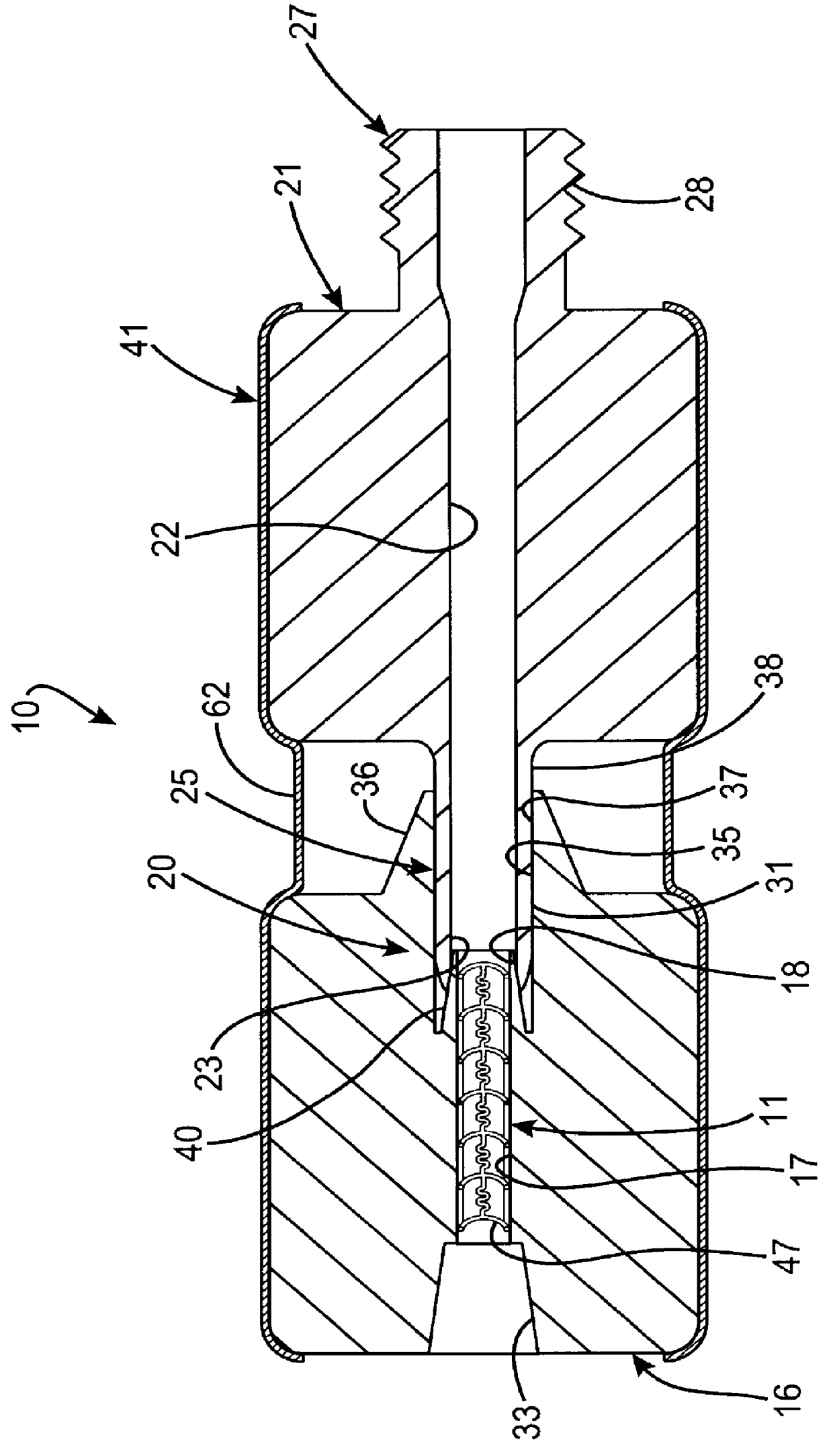
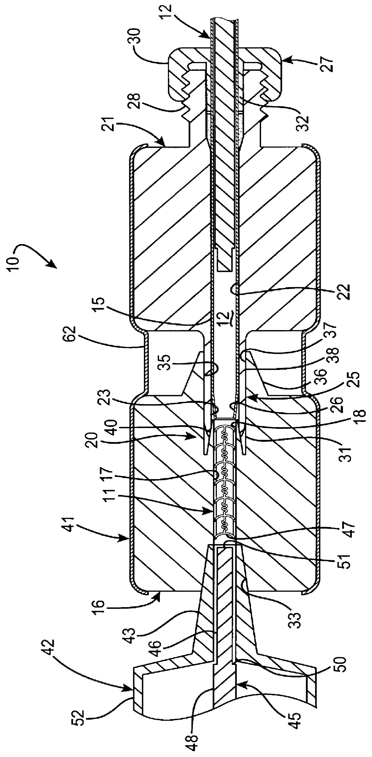
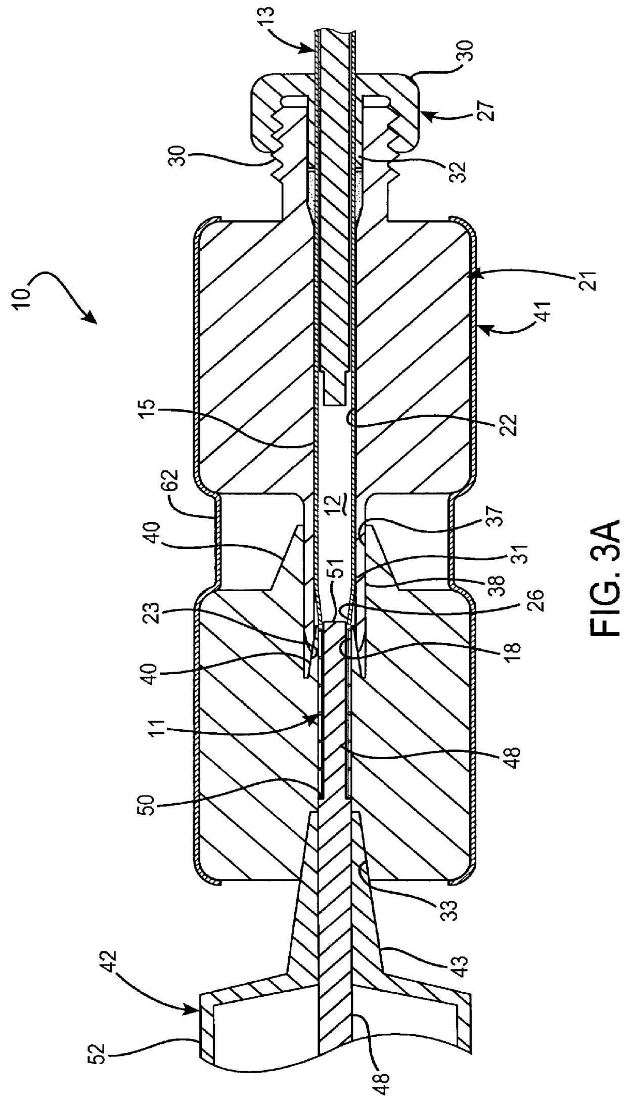
Attention is now directed to FIGS. 1 and 2, where a stent loading apparatus, generally designated 10, is provided for loading a self-expanding stent 11 into a bore portion 12 of a deployment device 13. Briefly, the deployment device is provided by a catheter or the like having an open ended distal tube or sheath 15 which is configured for sliding receipt and retainment of the stent 11 therein in a compressed or folded condition. The sten...


PUM


Abstract

A stent loading apparatus for loading a self-expanding radioactive stent into a bore of a deployment device in a compressed condition including a storage device defining an elongated first passage formed and dimensioned for sliding receipt of the stent therein. The first passage extends through the storage device and terminates at a stent transfer opening of a proximal coupling end thereof. A radiation shield defines an elongated second passage which terminates at a distal opening of a distal coupling end thereof. The distal coupling end of the radiation shield and the proximal coupling end of the storage device cooperate to align the distal opening of the shield in receiving communication with the stent transfer opening of the storage device. The second passage of the shield is formed and dimensioned for receipt of the deployment device therein in a manner positioning a mouth of the deployment device bore substantially adjacent the stent transfer opening of the storage device. Upon urging of the stent in a direction toward the shield, the radioactive stent may be slideably transferred from the first passage and into the mouth of the bore for retainment therein in the compressed condition.

Description

The present invention relates, generally, to intravascular stents and, more particularly, to stent loading assemblies for self-expanding radioactive stents.Percutaneous Transluminal Angioplasty (PTA) is a medical procedure for widening a stenosis or constriction of a bodily passage. The most common application is to widen the passage of a blood vessel, such as an artery, which has been constricted by the build-up of cholesterol fats or atherosclerotic plaque. When this medical procedure is applied to a coronary artery, it is referred to as Percutaneous Transluminal Coronary Angioplasty (PTCA).Typically, a tip mounted balloon of a balloon catheter is advanced over a guidewire to the stenosis. Once the balloon catheter is properly position, the balloon is inflated to compress the plaque against the vessel walls and widen the stenosis. Problems occur, however, when the dilatation of the occlusion forms fissures, flaps and / or dissections which may ultimately cause reclosure or restenosi...

Claims


Application Information

Patent Timeline
IPC IPC(8): A61F2/06A61N5/10A61F2/84A61M36/12
CPCA61F2/95A61N5/1002A61F2002/9522A61F2/9522A61F2/9526
Inventor CAMPBELL, THOMAS H.CHANG, ROBERT T.
Owner ISOSTENT
Why Eureka
Try Eureka