Switch having a temperature-dependent switching mechanism

a switching mechanism and switch technology, applied in the field of switches, can solve problems such as the inability of ceramic supports to sustain mechanical loads, the operating current rise, and the temperature of devices

Inactive Publication Date: 2000-07-18
HOFSASS MARCEL
View PDF7 Cites 12 Cited by
  • Summary
  • Abstract
  • Description
  • Claims
  • Application Information

AI Technical Summary

Problems solved by technology

The reason is that with electric motors in particular, it often happens that because of external influences the rotor comes to a stop or rotates only very slowly, which initially leads to a rise in the operating current, which in turn results in an elevation in the temperature of the device.
For one, the ceramic support cannot sustain mechanical loads: during transport in bulk, hairline cracks occur which can be detected up

Method used


Image

  • Switch having a temperature-dependent switching mechanism
  • Switch having a temperature-dependent switching mechanism

Examples


Embodiment Construction

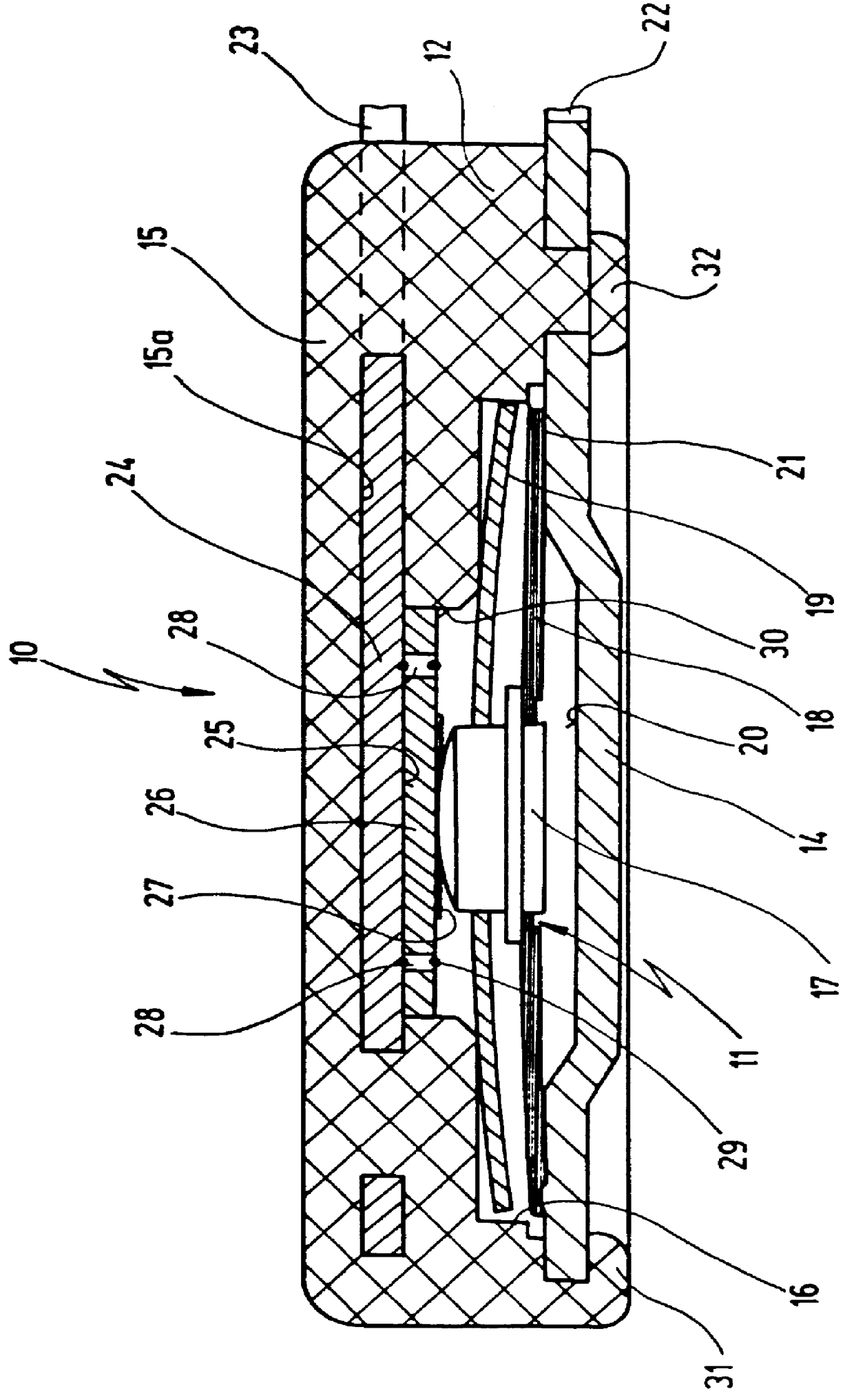
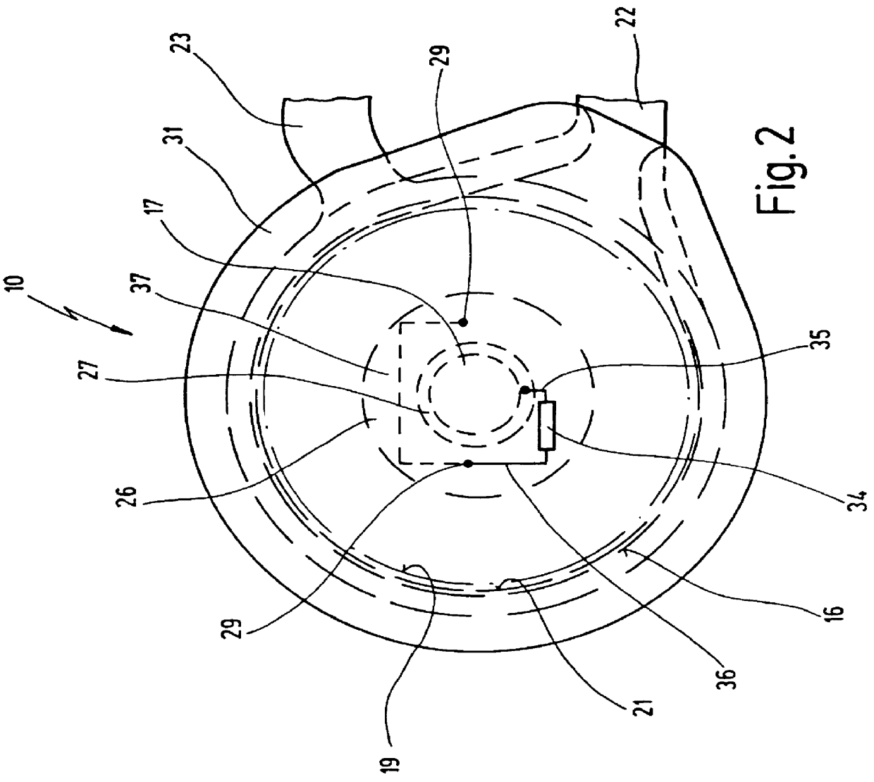
FIG. 1 shows, in a schematic side view, a new switch 10 which comprises a temperature-dependent switching mechanism 11 that is arranged in a housing 12.

Housing 12 has an electrically conducting base part 14 and a cup-like cover part 15, made of insulating material, which contains an annular space 16 into which temperature-dependent switching mechanism 11 is placed.

Switching mechanism 11 comprises a movable contact element 17 which is carried by a spring disk 18 and over which a bimetallic snap disk 19 is placed.

The electrically conducting base part 14 constitutes, with its inner side, an electrode 20 against which spring disk 18 braces with its rim 21. Base part 14 transitions integrally into a first external terminal 22 which is thereby connected in electrically conducting fashion to spring disk 18 and thus to movable contact element 17.

A second external terminal 23 of switch 10 is integrally connected to an insert-molded electrode 24 which is arranged on an inner base 15a of cover...


PUM


Abstract

A switch is described, having a housing 12 which receives a temperature-dependent switching mechanism 11 and which has a first housing part 15 on whose inner base 25 a first electrode 24 connected to a first external terminal 23 is arranged, as well as a second housing part 14, closing off the first housing part 15, that comprises a second electrode 20 connected to a second external terminal 22. The switching mechanism 11 creates, as a function of its temperature, an electrically conducting connection between the first and the second electrode 24, 20. A series resistor 34 is arranged in the housing 12, geometrically and electrically between the switching mechanism 11 and one of the two electrodes 20, 24.

Description

1. Field of the InventionThe present invention relates to a switch having a housing which receives a temperature-dependent switching mechanism and which has a first housing part on whose inner base a first electrode connected to a first external terminal is arranged, as well as a second housing part, closing off the first housing part, that comprises a second electrode connected to a second external terminal, the switching mechanism creating, as a function of its temperature, an electrically conducting connection between the first and the second electrode.2. Related Prior ArtA switch of this kind is known from DE 196 09 310 A1.In the case of the known switch, the first housing part is produced from insulating material, into which the first electrode is embedded as an integral constituent by insert-molding or encapsulation. This first housing part is closed off by a second housing part in the form of a base made of electrically conductive material, the inner side of which acts as a s...

Claims


Application Information

Patent Timeline
IPC IPC(8): H01H37/00H01H81/00H01H37/54H01H81/02
CPCH01H37/5427H01H81/02
Inventor HOFSASS, MARCEL
Owner HOFSASS MARCEL
Why Eureka
Try Eureka