Outboard motor

a technology for outboard motors and motors, applied in the field of outboard motors, can solve problems such as reducing the physical size of engines

Inactive Publication Date: 2000-08-01
SANSHIN KOGYO CO LTD
View PDF19 Cites 17 Cited by
  • Summary
  • Abstract
  • Description
  • Claims
  • Application Information

AI Technical Summary

Problems solved by technology

While this engine layout reduces the longitudinal dimension of the engine in an attempt to provide a compact engine design, the layout inhibits the arrangement of other engine components on the engine in a manner further reducing the engine's physical size.

Method used


Image

  • Outboard motor
  • Outboard motor
  • Outboard motor

Examples


Embodiment Construction

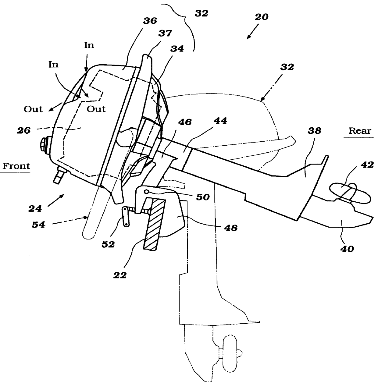
FIG. 1 illustrates a marine outboard drive 20 which is configured in accordance with preferred embodiment of the present invention. In the illustrated embodiment, the outboard drive 20 is depicted as a portable outboard motor for mounting on a transom 22 at the stem of a watercraft. It is contemplated, however, that the present engine layout and cowling design can be incorporated with other types of outboard motors as well.

In order to facilitate the description of the present outboard motor 20, the terms "front" and "rear" are used to indicate positions of the outboard motor components relative to a fixed datum: the transom 22 of the watercraft. Thus, as used herein, "front" refers to a position or a side closer to the watercraft transom 22, and "rear" refers to a position or side distanced from the transom 22. Some of the figures included labels to further aid the reader's understanding.

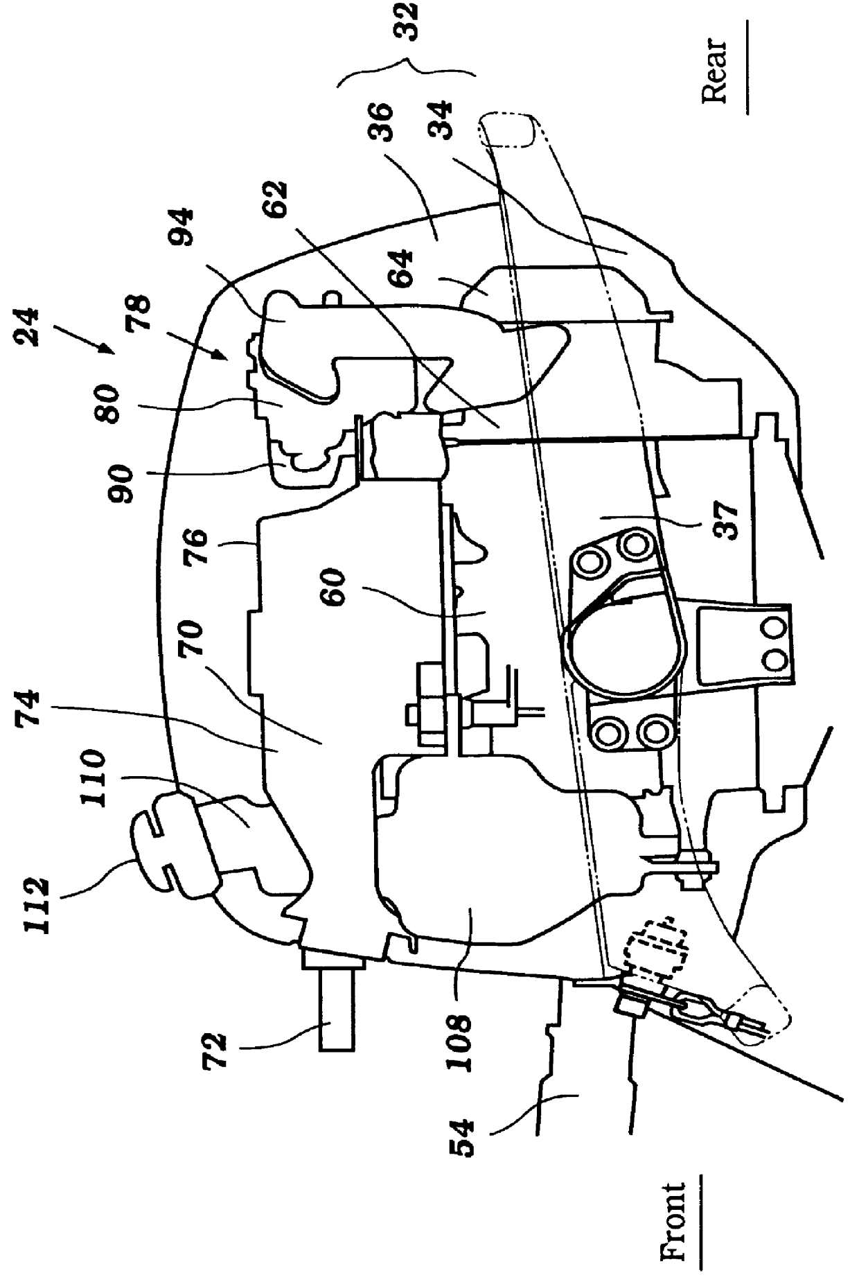
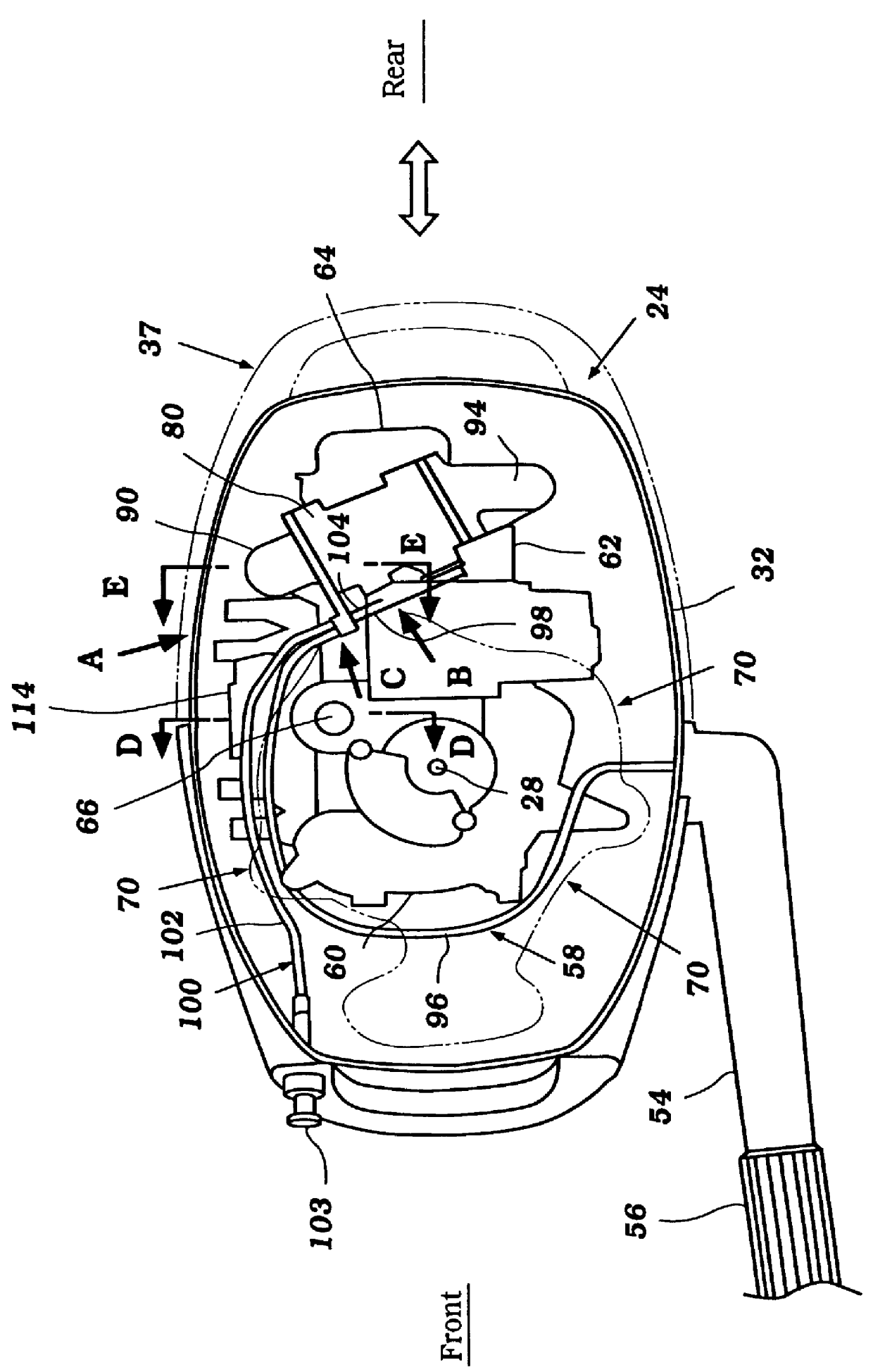
With initial reference to FIG. 1, the outboard motor 20 has a power head 24 that includes an int...


PUM


Abstract

An outboard motor includes an improved engine layout to provide a compact power head while simplifying the arrangement of components on the engine. In one mode, an induction system of the engine includes a carburetor that is arranged over a cylinder head. An intake pipe connects the carburetor to an intake port of the cylinder head. The pipe has generally a U-shape and loops around the upper side edge of the cylinder head. An air intake device is arranged upstream of the carburetor to supply air thereto. The air intake device includes a downward facing air intake opening that is located along a side of the engine below the upper end. This arrangement of the induction system that extends over the upper side of the engine produces a compact assembly without overly complicating the arrangement of other components on the engine, such as, for example, a manual starter device. With the present engine layout, the manual starter device is positioned on an upper side of the engine in front of the carburetor near a crankshaft of the engine. The air intake opening faces a lower air vent formed in a cowling below the engine. Cool air flows through the lower air vent and is drawn into the air intake opening for engine operation. This flow of cool air also cools the engine. The cowling also includes an upper vent to expel warm air from about the carburetor on the upper side of the cowling and to promote a current of air across the engine for cooling purposes.

Description

1. Field of the InventionThe present invention relates to an outboard motor, and more particularly to an improved engine layout within a cowling of an outboard motor.2. Description of Related ArtOutboard motors typically include a power head supported by an upper housing. A clamping bracket usually secures the upper housing to a transom of an associated watercraft. The upper housing also supports a lower unit that includes a propeller or similar propulsion device. An engine within a cowling of the power head drives the propeller via a drive train. The drive train commonly includes a drive shaft, which extends generally vertically through the upper housing, and a propeller shaft, which lies at about a 90 degree shaft angle with the drive shaft. A gear set couples the drive shaft to the propeller shaft. The propeller shaft extends in generally a horizontal direction and support the propeller at an aft end of the propeller shaft. Power from the engine is transferred from the drive shaf...

Claims


Application Information

Patent Timeline
Patent Type & Authority Patents(United States)
IPC IPC(8): F02B75/22F02B75/16F02B75/00F02B61/00F02B61/04F02M35/16F02M35/00F02M35/104F02M35/116F02B75/02F02B75/18F01P1/00F02M35/10
CPCF02B61/045F02B75/16F02B75/22F02M35/10111F02M35/10196F02M35/167F01P2001/005F02B2075/027F02B2075/1808F02B2075/1812F02M35/116
Inventor KAWAMUKAI, KENJINOZUE, TOSHIHIROKAMEOKA, KENTAROKITAJIMA, KAZUYUKI
Owner SANSHIN KOGYO CO LTD
Why Eureka
Try Eureka