Surgical instrument with an apparatus for limiting the transfer of a force

a technology for surgical instruments and apparatuses, applied in the field of surgical instruments with limiting force transfer, can solve the problems of operator exerting a closing force which exceeds the force that can be safely sustained by the mouth parts, aforesaid overloading even the breakage of the mouth parts, so as to prevent overloading of the working parts of the surgical instrumen

Inactive Publication Date: 2000-08-01
KARL STORZ GMBH & CO KG
View PDF2 Cites 69 Cited by
  • Summary
  • Abstract
  • Description
  • Claims
  • Application Information

AI Technical Summary

Benefits of technology

to create an apparatus with which overloads on the working parts of a surgical instrument can be reliably prevented.
This feature has the advantage that the apparatus can be arranged in integrated and thus also protected fashion in the region of the handle at the proximal end of the shaft, so that in the region of the shaft and the mouth parts as such, there is no diametrical enlargement at all due to the additional installation of the apparatus.

Problems solved by technology

Because of the miniaturization of the mouth parts necessary for minimally invasive surgery, they are sensitive to loads, since for given hand forces the sustainable forces become smaller due to miniaturization.
In the case of cutting and in particular cut-through mouth parts there may be a risk, if instead of an easily cut soft tissue element a piece of cartilage or bone ends up between the mouth points, that the operator will exert a closing force which exceeds the force that can be safely sustained by the mouth parts.
If overloading due to the exertion of excessive hand force, and thus high loading of the mouth parts, occurs frequently, this can cause material fatigue in the mouth part region and even breakage of the mouth parts.
There exists in this context the risk that the aforesaid breakage of the mouth parts due to overloading might occur during the operation.
This can result in uncontrolled damage to tissue and organs in the operative area.
Force limitation is accomplished by the fact that at the maximum applicable hand force, the spreading is limited by the material properties and configuration of the housing and ring.

Method used


Image

  • Surgical instrument with an apparatus for limiting the transfer of a force
  • Surgical instrument with an apparatus for limiting the transfer of a force
  • Surgical instrument with an apparatus for limiting the transfer of a force

Examples


Embodiment Construction

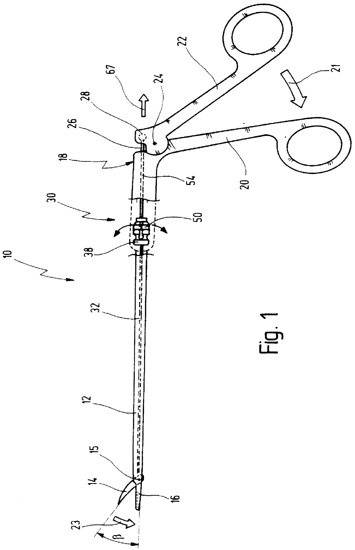
FIG. 1 shows a surgical instrument in the form of a grasping and dissection forceps, designated in its entirety with the reference number 10.

Forceps 10 has an elongated tubular shaft 12 at whose distal end two mouth parts 14 and 16 are arranged.

Mouth part 16 is rigidly joined to shaft 12, and mouth part 14 is arranged pivotably about an axis 15.

A handle 18 is arranged at the proximal end of shaft 12.

Handle 18 has a stationary handle element 20 that is joined immovably to shaft 12. A movable handle element 22 is arranged, pivotably about a hinge axis 24, on stationary handle element 20.

A rod-shaped actuation element 26, which is joined at the distal end to movable mouth part 14 at a slight distance from its pivot axis 15, is arranged so as to pass through shaft 12. At the proximal end, actuation element 26 extends out beyond stationary handle element 20 and is received in a ball-and-socket joint 28 of movable handle element 22. In FIG. 1 mouth parts 14 and 16 are open and thus enclos...


PUM


Abstract

An surgical instrument comprises a movable actuation element, at least one working part moved by said actuation element, an apparatus for limiting a transfer of a force transferred via said actuation element to said at least one working part. Said apparatus has at least one wedge surface associated to said actuation element, said wedge surface rising perpendicular to its movement when moving said actuation element. A housing is provided which can be spread apart by said wedge surface by movement thereof, and an elastically spreadable ring circumferentially surrounds said housing in its spreading section, said elastically spreadable ring can close said spread housing when said wedge surface is moved out of its spreading engagement with said housing.

Description

1. Field of the InventionThe present invention relates to an apparatus for limiting the transfer of force to surgical instruments.The invention further concerns surgical instruments which are equipped with an apparatus of this kind.Surgical instruments of this kind may be grasping, holding, and dissection forceps, scissors, or other instruments in which working part, usually mouth parts, are moved by manual force via an actuation element that can be moved back and forth.2. Related Prior ArtGrasping, holding, and dissection forceps are known, for example, from the catalog "Endoskopische Chirurgie [Endoscopic surgery], 2nd edition, 1 / 94, section 4, Praparier- und Fa.beta.zangen [Dissection and grasping forceps]" of Karl Storz GmbH & Co., Tuttlingen, Germany.These known forceps have an elongated cylindrical shaft at whose distal end at least two mouth parts are arranged. Arranged at the proximal end of the shaft is a handle which has the form of two scissor-like handle elements. One of...

Claims


Application Information

Patent Timeline
Patent Type & Authority Patents(United States)
IPC IPC(8): A61B17/28A61B19/00
CPCA61B17/29A61B19/30A61B90/03
Inventor BOCHE, HARTMUT
Owner KARL STORZ GMBH & CO KG
Why Eureka
Try Eureka