Machine for applying a protective material onto a pipe

Inactive Publication Date: 2000-08-08
TEK RAP
View PDF51 Cites 18 Cited by
  • Summary
  • Abstract
  • Description
  • Claims
  • Application Information

AI Technical Summary

Problems solved by technology

Corrosion protection extends the life of the pipe and has found particular application in pipelines where miles upon miles of pipes are laid and where replacing and/or repairing the pipes would be difficult, time consuming and costly.
Although wrapping the pipe with a

Method used


Image

  • Machine for applying a protective material onto a pipe
  • Machine for applying a protective material onto a pipe
  • Machine for applying a protective material onto a pipe

Examples


Example

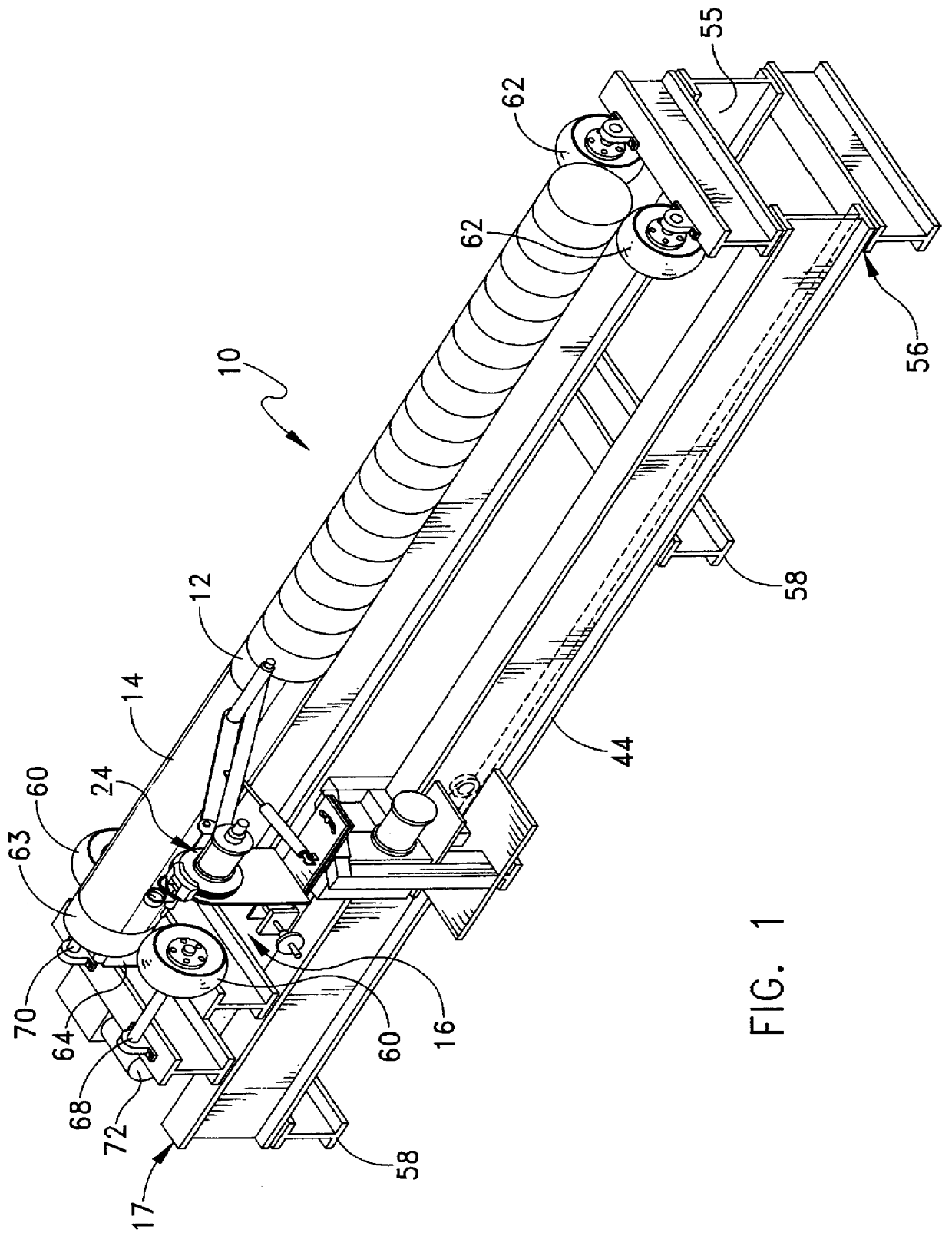
A machine 10 for applying a protective layer of material 12 onto a pipe 14 is illustrated in FIG. 1. The machine includes a brake tension unit 16 for applying a constant tension to the protective material in order to elongate the material as it is applied onto the pipe and a base unit 17 for supporting and rotating the pipe. Elongation of the protective material by the brake tension unit allows the material to be applied to the pipe in a substantially wrinkle free and continuous manner so as to effectively adhere the protective layer of material to an outer surface of the pipe while preventing air and / or moisture from becoming entrapped between the protective layer and the pipe. By applying the protective material in this manner, improved corrosion resistance is achieved.

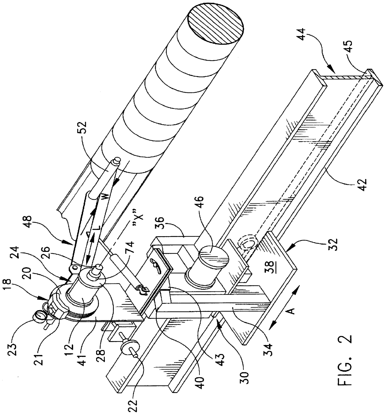
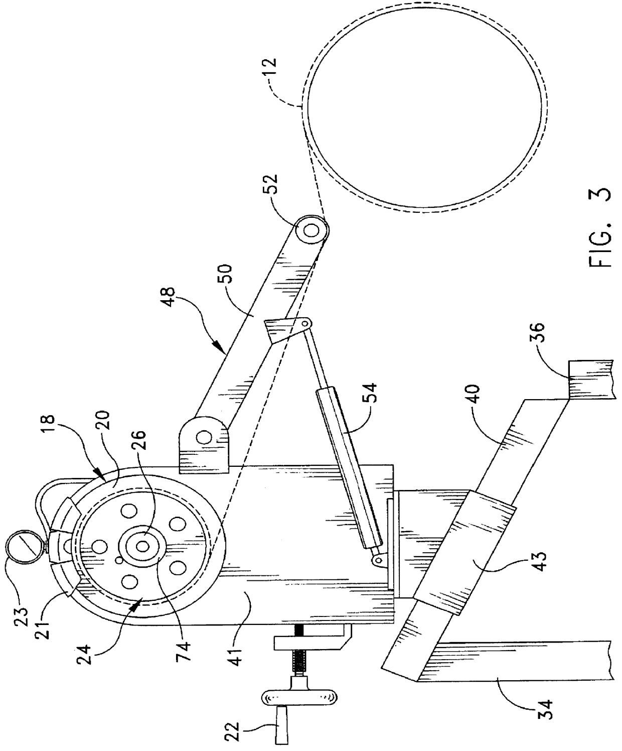
In the present embodiment, the brake tension unit 16 preferably includes a conventional rotor disc brake 18 (FIG. 2), such as those used in automobiles, having a rotor 20 and two disc pads mounted within a housing 2...


PUM

PropertyMeasurementUnit
Forceaaaaaaaaaa
Pressureaaaaaaaaaa
Angleaaaaaaaaaa

Abstract

A machine for applying one or more protective layers of material onto a tubular member, for example a pipe, in a substantially wrinkle free and continuous manner. The machine includes a brake tension unit for applying a constant tension to the protective material in order to neck down the material as it is applied onto the pipe, and a base unit for supporting and rotating the pipe. The constant brake tension unit preferably includes a conventional disc brake and a mounting arm for holding a core of material in engagement with the brake tension unit. Pressure applied to the rotor slows rotation of the rotor and the attached core which restricts the unwinding of the protective material from the core. Thus, as the material attempts to unwind from the core a preselected force is applied to resist the unwinding. The material is therefore placed under tension and, due to the nature of the protective material, the material elongates and necks down under the applied pressure. The brake unit may also include a tension arm for holding the protective layer against the pipe to prevent slack in the material as it is being applied.

Description

The invention relates generally to a machine for applying a protective layer onto a tubular member, such as pipes and the like, and more particularly to a machine including a constant brake tension unit for applying one or more layers of a protective material spirally onto a pipe in a wrinkle free and continuous manner.BACKGROUND OF RELATED ARTWhen utilizing pipes for various applications it is often desirable to coat the pipe with a layer of material in order to protect the pipe against corrosion or to provide other types of protection to the pipe, for example in order to insulate the pipe. Corrosion protection extends the life of the pipe and has found particular application in pipelines where miles upon miles of pipes are laid and where replacing and / or repairing the pipes would be difficult, time consuming and costly. Various types of machines are known to apply coatings or protective layers of material to the outer wall of a tubular member, such as a pipe. For example, as discl...

Claims


Application Information

Patent Timeline
IPC IPC(8): B29C63/10B29C53/80B29C53/00B29C63/02B65H81/08B65H81/00B29C53/66B29C55/00
CPCB29C53/8016B29C63/105B65H81/08B29C53/66B29C55/00B29L2009/00B29L2023/22
Inventor DEMORE, JOHN C.
Owner TEK RAP
Why Eureka
Try Eureka