Exhaust gas purifying system of internal combustion engine

a technology of exhaust gas purification system and internal combustion engine, which is applied in the direction of electrical control, process and machine control, instruments, etc., can solve the problems of nox discharge to the open air, nox released from the converter would not be sufficiently reduced, and exhaust gas purification systems have failed to exhibit a satisfied rich spike control

Inactive Publication Date: 2000-08-15
NISSAN MOTOR CO LTD
View PDF7 Cites 43 Cited by
  • Summary
  • Abstract
  • Description
  • Claims
  • Application Information

AI Technical Summary

Problems solved by technology

However, in the exhaust gas purifying systems of the type using the above-mentioned rich spike control, the rich spike action is conducted without making a strict consideration on a time-caused deterioration of the NOx-occluded converter and a time-caused and/or random changing of the NOx exhausting characteristics of the engine.
Thus, due to this reason, such exhaust gas purifying systems have failed to exhibit a satisfied rich spike control.
However, if the rich level at the initial stage of the rich spike control is not sufficiently high and thus the amount of HC and CO (which serve as reducers for NOx) in the exhaust gas is not sufficient, NOx released

Method used


Image

  • Exhaust gas purifying system of internal combustion engine
  • Exhaust gas purifying system of internal combustion engine
  • Exhaust gas purifying system of internal combustion engine

Examples


first embodiment

Referring to FIGS. 1 to FIG. 9D, there is shown the present invention.

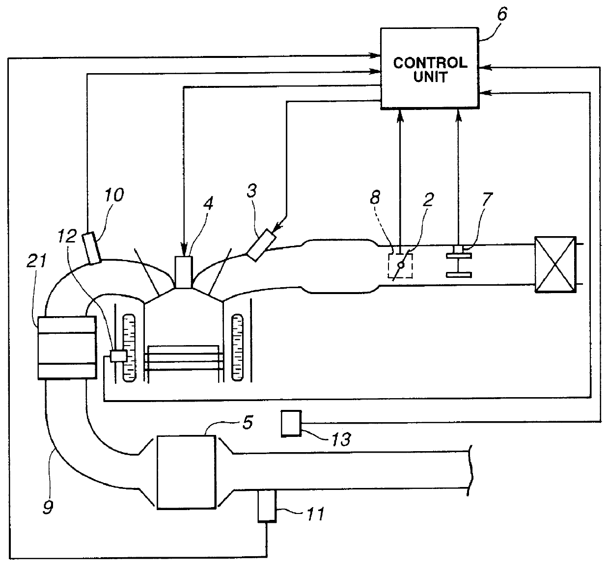
In FIG. 1, there is schematically shown an internal combustion engine 1 to which the present invention is practically applied. A throttle valve 2 is installed in an intake passage to feed a combustion chamber of the engine 1 with a metered air. A fuel injector 3 is projected into the intake passage to inject a metered fuel in the intake passage. Thus, before entering the combustion chamber, the metered fuel and the metered air are mixed to form a combustible air / fuel mixture. The air / fuel mixture led into the combustion chamber is ignited by an ignition plug 4 and burnt to produce an exhaust gas. The exhaust gas is led to an exhaust passage 9 and treated or purified by an NOx-occluded converter 5 (viz., NOx-occluded type three-way catalytic converter) before discharging to the open air. As is mentioned hereinabove, the NOx-occluded converter 5 has such a performance that when the exhaust gas from the engine shows ...

second embodiment

Referring to FIGS. 12 to 17, there is shown the present invention.

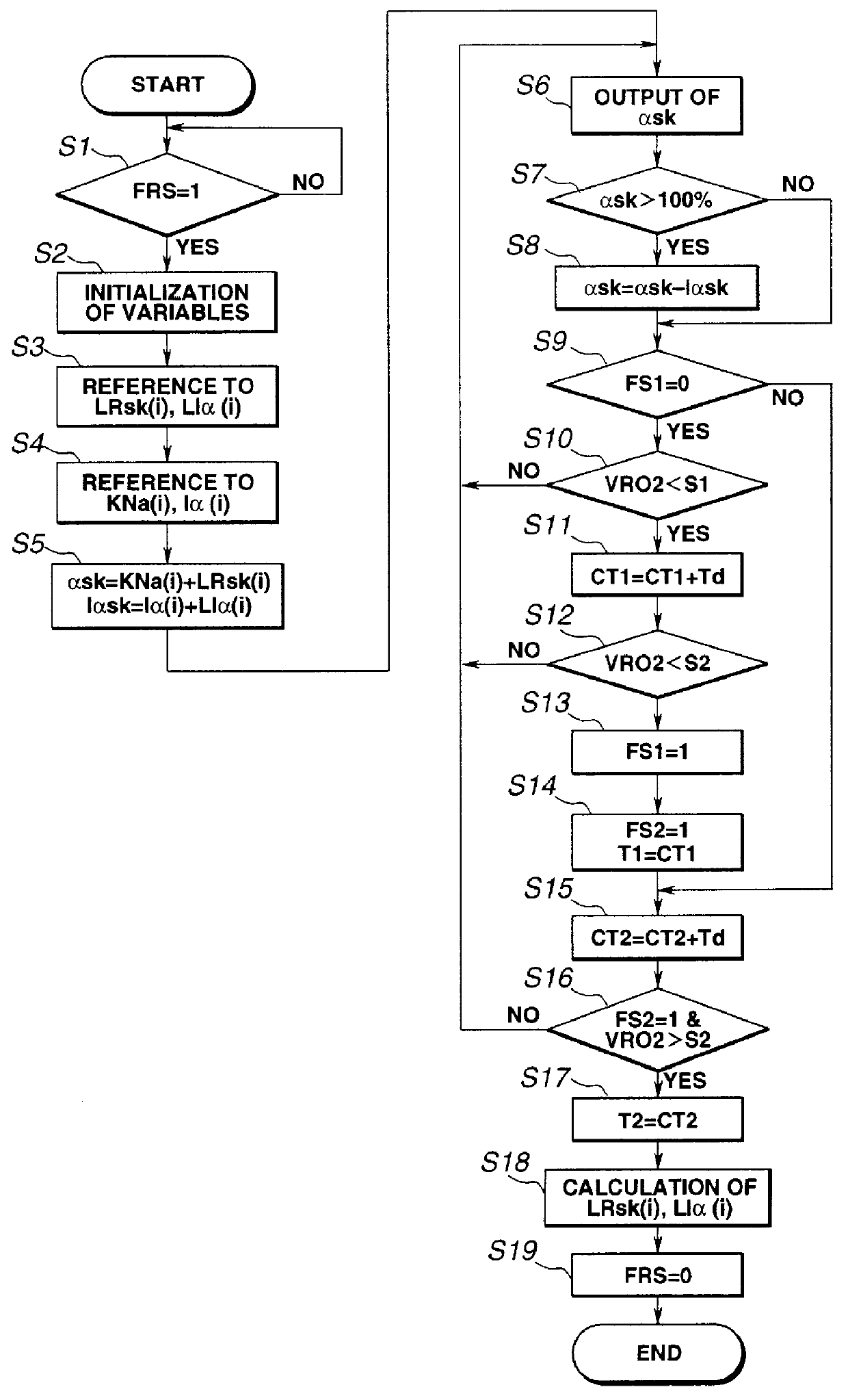
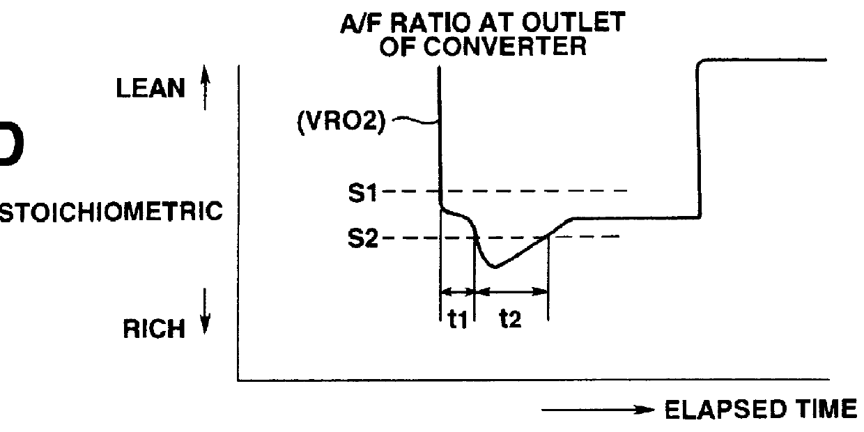
The rich spike learning control of the second embodiment is depicted by the flowchart of FIG. 12 and the characteristics of the control are depicted by the time charts of FIGS. 13A to 13D.

In the flowchart of FIG. 12, at step S101, similar to the first step S1 of the above-mentioned first embodiment, judgment is carried out as to whether a condition for effecting the NOx-reduction treatment has been established or not. That is, if the condition for the NOx-reduction treatment has been established, that is, when the flag "FRS" has been set to 1 (one), the operation flow goes to step S102 where variables used in the control are initialized. For example, an after-mentioned rich condition judging flag "FS" for judging a rich condition of the exhaust gas detected by the second air / fuel ratio sensor 11, an after-mentioned minimum value "VRmin" and a value of a counter "CTR" are reset to 0 (zero).

Then, the operation flow goes...


PUM


Abstract

To optimally operate a NOx-occluded type catalytic converter installed in an exhaust passage of an internal combustion engine, there are employed an air/fuel ratio sensor for detecting an exhaust air/fuel ratio of the exhaust gas downstream of the converter; and a control device for controlling an air/fuel ratio of a combustible mixture fed to the engine. The control device comprises a first section for causing the converter to effect NOx-reduction treatment by making the air/fuel ratio of the combustible mixture richer and/or stoichiometric; and a second section for learning and correcting the condition of the NOx-reduction treatment, based on the exhaust air/fuel ratio detected by the sensor under the NOx-reduction treatment.

Description

1. Field of the InventionThe present invention relates in general to exhaust gas purifying systems of an internal combustion engine and more particularly to exhaust gas purifying systems of a type which has a NOx-occluded type three-way catalytic converter installed in an exhaust passage extending from the engine. More specifically, the present invention is concerned with a control system employed in the exhaust gas purifying system of the above-mentioned type for controlling an air / fuel ratio of a mixture to a level appropriate for effectively purifying NOx in the exhaust gas.2. Description of the Prior ArtInternal combustion engines having a NOx-occluded type three-way catalytic converter installed in an exhaust passage have been known, one of which is described in Japanese Patent First Provisional Publication 7-139397.As is known, the NOx-occluded type three-way catalytic converter has such a performance that when the exhaust gas from the engine shows a higher air / fuel ratio (viz...

Claims


Application Information

Patent Timeline
IPC IPC(8): F01N3/08F01N3/20F02D41/02F02D41/14F01N7/02F01N7/00F01N13/02
CPCF01N3/0814F01N3/0842F01N3/0871F02D41/0275F02D41/1402F01N13/009F01N2250/12F01N2430/06F01N2560/025F01N2610/03Y02T10/24Y02T10/12F01N3/18F01N3/24F02D41/1438
Inventor ISHIZUKA, YASUJINISHIZAWA, KIMIYOSHI
Owner NISSAN MOTOR CO LTD
Why Eureka
Try Eureka