Inductor and production method thereof

a technology of inductor and production method, which is applied in the direction of transformer/inductance coil/winding/connection, inductance with magnetic core, etc., can solve the problem of deteriorating the electric characteristics of the inductor, generating cracks in the ceramic, and the electric resistance of the internal conductor (coil) cannot be lower than a certain level

Inactive Publication Date: 2000-08-15
MURATA MFG CO LTD
View PDF5 Cites 44 Cited by
  • Summary
  • Abstract
  • Description
  • Claims
  • Application Information

AI Technical Summary

Problems solved by technology

As a result, the electric resistance of the internal conductor (coil) cannot be lower than a certain level.
This stress generates cracks in the ceramic.
The stress that remains in the inductor and the stress generated by the usage condition, as mentioned above, not only deteriorate the electric characteristics of the inductor, but may also generate cracks in the ceramic, depending upon the size of the stress.
Moreover, repetition of application and release of stress also serves as the cause of crack generation in the ceramic.
Crack generation leads to an increase in the leakage flux which further deteriorates the characteristics of the inductor.

Method used


Image

  • Inductor and production method thereof
  • Inductor and production method thereof
  • Inductor and production method thereof

Examples


Embodiment Construction

In the following, the exemplary embodiments of the present invention are explained with reference to the drawings.

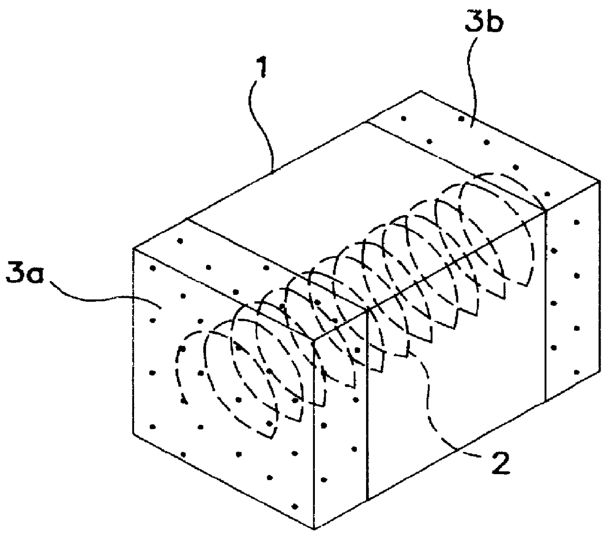
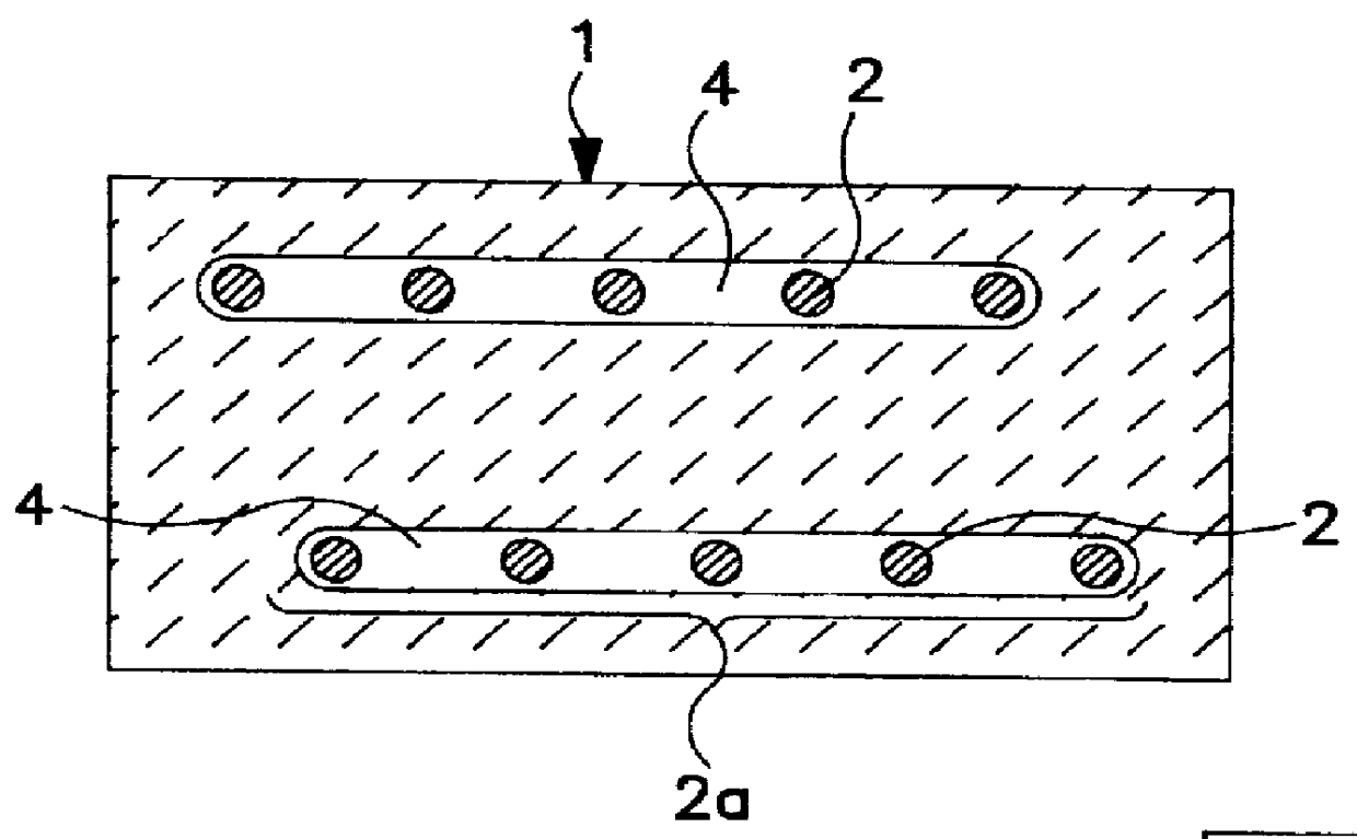
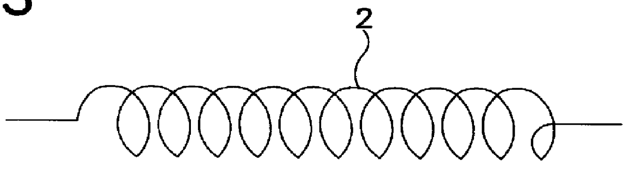
FIG. 1 is a plan cross-sectional view of an element (i.e., chip element) comprising an inductor according to an exemplary embodiment of the present invention. FIG. 2 is a lateral cross-sectional view thereof. FIG. 3 is a perspective view of the inductor of the present invention.

As shown in FIG. 3, the inductor is provided with an internal conductor 2. The internal conductor 2, according to an exemplary embodiment of the present invention, is a metal wire formed in a coil-like shape. The internal conductor is formed within an element (chip element) 1 made from a ceramic material and having external electrodes 3a, 3b conductive with the internal conductor 2 at both ends of the element 1.

As is evident from the lateral view of FIG. 2, a substantially cylindrical (circular cylindrical) gap 4 is formed so as to surround the coil-like internal conductor (coil) 2. The internal c...


PUM

PropertyMeasurementUnit
thickaaaaaaaaaa
diameteraaaaaaaaaa
magneticaaaaaaaaaa

Abstract

The present invention provides a system and method for producing a reliable inductor having an internal conductor with a small electric resistance. A metal wire formed in a nonlinear shape is used as the internal conductor. In an exemplary embodiment of the invention, the internal conductor has a coil-like shape with portions adjacent to each other with respect to the axial direction of the coil being positioned in a substantially cylindrical gap formed in the axial direction of the coil. By providing a gap around the internal conductor, stress between the internal conductor and a ceramic material surrounding the conductor can be eliminated. As a result, the characteristic deterioration or crack generation in the inductor chip is eliminated. Moreover, the leakage flux among the coil pitches of the conductor is reduced, thereby improving the characteristics of the inductor.

Description

This application corresponds to Japanese Patent Application Nos. 9-244679, filed Aug. 25, 1997, and 9-247624, filed on Aug. 27, 1997, and both of which are hereby incorporated by reference in their entireties.1. Field of the InventionThe present invention relates generally to inductors and, more particularly, to a system and method for producing an inductor with improved characteristics.2. Description of the Related ArtFIGS. 7A and 7B illustrate a conventional layered-type inductor. This type of inductor is an example of a surface mounting type inductor. As illustrated in FIGS. 7A and 7B, the layered-type inductor is provided with a layered-type coil 52 formed by interconnecting a plurality of internal conductors 52a. The layered-type inductor also includes external electrodes 53a, 53b which are connected to respective end portions of the coil 52.As illustrated in FIGS. 7A and 7B, such a layered-type inductor is commonly produced by laminating a plurality of ceramic green sheets 54 ...

Claims


Application Information

Patent Timeline
Patent Type & Authority Patents(United States)
IPC IPC(8): H01F17/02H01F17/03H01F17/04C04B35/64H01F17/06H01F27/32H01F41/04
CPCH01F17/03H01F17/045Y10T29/49071Y10T29/4902Y10T29/49144Y10T29/49076
Inventor YAMAMOTO, TAKAHIROMORIMOTO, TADASHI
Owner MURATA MFG CO LTD
Why Eureka
Try Eureka