Air conditioning apparatus for vehicle seat

a technology for air conditioning apparatus and vehicle seat, which is applied in vehicle heating/cooling devices, refrigeration machines, process and machine control, etc., can solve the problems of sensor adding cost to the air conditioning apparatus for the vehicle seat, difficult to be provided within the seat, and overheating may be given to the passenger

Inactive Publication Date: 2000-08-22
DENSO CORP
View PDF12 Cites 144 Cited by
  • Summary
  • Abstract
  • Description
  • Claims
  • Application Information

AI Technical Summary

Problems solved by technology

However, during a heating mode, when warm air is continually blown toward the seat so that temperature of a surface sheet of the seat becomes high, over-heating may be given to the passenger.
However, the temperature sensor adds cost to the air conditioning apparatus for the vehicle seat, and is difficult to be provided within the seat.
Further, in the conventional air conditioning apparatus, conditioned air is not blown into the seat before a unit blower of the front air conditioning unit is operated, warm air is not immediately blown from the surface sheet of the seat, and the seat is not quickly heated.

Method used


Image

  • Air conditioning apparatus for vehicle seat
  • Air conditioning apparatus for vehicle seat
  • Air conditioning apparatus for vehicle seat

Examples


first embodiment

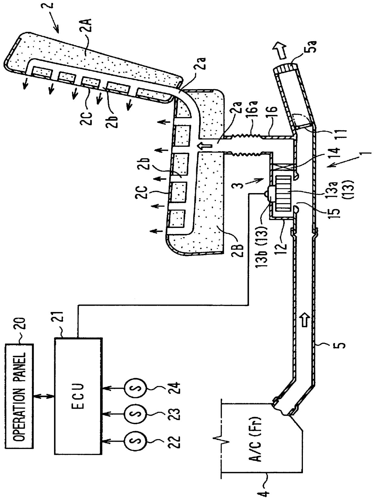
In the first embodiment, a rear foot duct for supplying warm air from the front air conditioning unit 4 toward the foot area of a passenger seated on a rear seat is used as the seat duct 5, for example. A rear foot air outlet 5a for the rear seat of the passenger compartment is provided in the seat duct 5 at a most downstream air side, and a switching door 11 for opening and closing the foot air outlet 5a is disposed in the seat duct 5 at an upstream air side of the rear foot air outlet 5a. The switching door 11 is rotated between the solid line position and the chain line position in FIG. 1, and is driven by an actuator (not shown) such as a servomotor. The actuator for the switching door 11 is electrically controlled by the ECU 21. When the seat switch of the operation panel 20 is turned on, the switching door 11 is rotated to the solid line position in FIG. 1 to close the rear foot air outlet 5a. On the other hand, when the seat switch of the operation panel 20 is turned off, the...

second embodiment

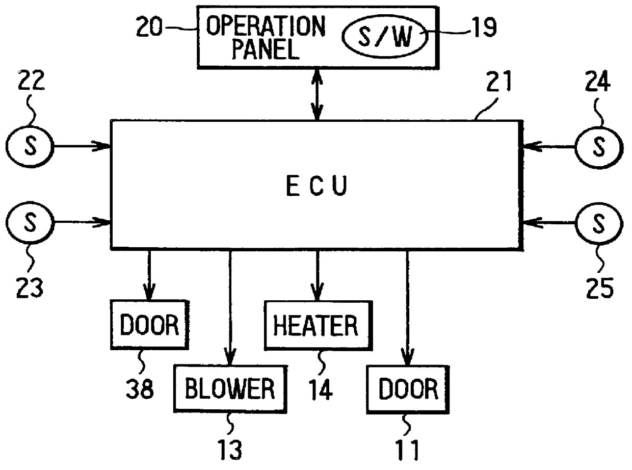
In the second embodiment, as shown in FIG. 5, when a seat switch 19 provided in the operation panel 20 is turned on, operations of the switching door 8, the seat blower 13, the electrical heater 14 and the switching door 11 are controlled by the ECU 21. In the ECU 21, the target air temperature (TAO) is calculated based on operation signals output from switch operations of the operation panel 19, and various sensor signals output from the inside air temperature sensor 22, the outside air temperature sensor 23, the sunlight temperature sensor, a water temperature sensor 25 for detecting the temperature of the engine-cooling water, and the like. According to the calculated TAO, the ECU 21 outputs control signals to actuators for the switching door 38, the seat blower 13, the electrical heater 14 and the switching door 11.

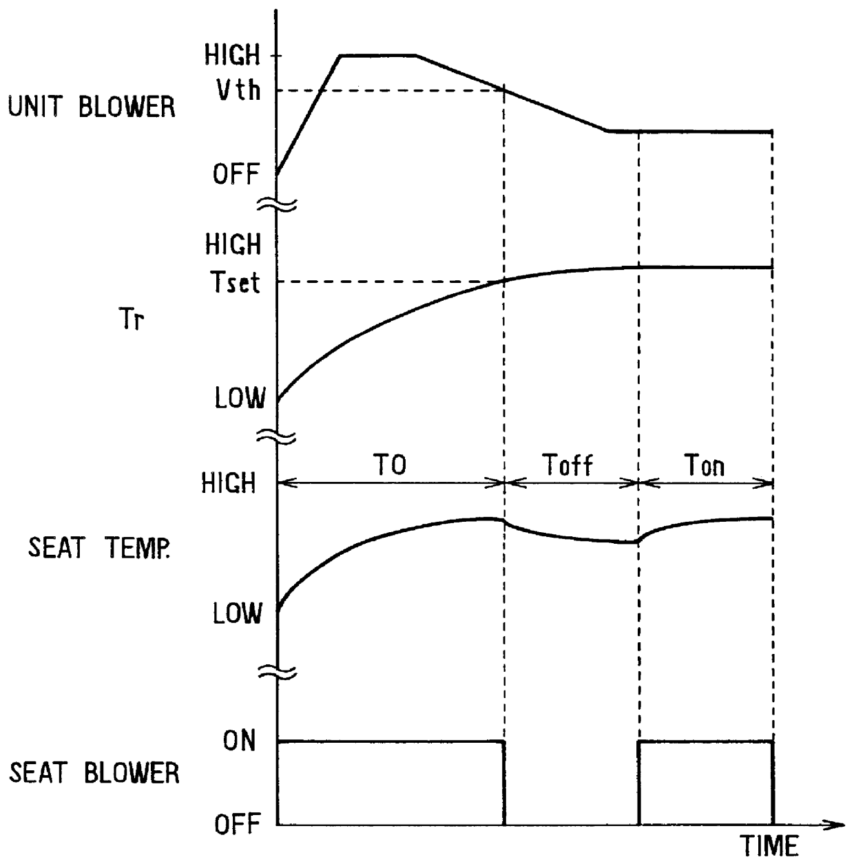
Next, control processes of the air conditioning apparatus 1A for the vehicle seat according to the second embodiment of the present invention will be described based ...


PUM


Abstract

An air conditioning apparatus for a vehicle seat includes a seat blower unit disposed in a lower side of the seat, and a seat duct for leading air from an air conditioning unit to the seat through the seat blower unit. In the air conditioning apparatus, it can be determined that heat load of a passenger compartment is decreased to a predetermined value based on an operation state of a unit blower of the air conditioning unit, and the seat blower is stopped when the heat load is decreased to the predetermined value. Further, the seat blower is turned on or off according to the heat load of the passenger compartment, so that temperature of the seat can be controlled within a predetermined range. On the other hand, even when the unit blower is stopped when a water temperature of a heating unit of the air conditioning unit is lower than a set temperature, the seat blower unit and an electrical heater disposed in the seat duct are operated so that air passing through the heating unit is heated by the electrical unit and is blown into the seat by the seat blower unit.

Description

This application is related to and claims priority from Japanese Patent Applications No. Hei. 10-61203 filed on Mar. 12, 1998, and No. Hei. 10-76843 filed on Mar. 25, 1998.1. Field of the Invention:The present invention relates to an air conditioning apparatus for a vehicle seat, which supplies air toward an air passage in the seat to be blown air toward a passenger seated on the seat from a surface sheet of the seat.2. Description of Related Art:In a conventional air conditioning apparatus for a vehicle seat described in JP-U-59-164552, air conditioned in a front air conditioning unit is supplied to an air chamber within the seat through a seat duct, and air in the air chamber is blown from a surface sheet of the seat to improve pleasant feeling for a passenger seated on the seat in the passenger compartment. However, during a heating mode, when warm air is continually blown toward the seat so that temperature of a surface sheet of the seat becomes high, over-heating may be given t...

Claims


Application Information

Patent Timeline
Patent Type & Authority Patents(United States)
IPC IPC(8): B60H1/00B60N2/56B60N2/90
CPCB60H1/00285B60N2/5628B60N2/5657B60H2001/003Y10S454/907
Inventor YOSHINORI, TAKESHIAOKI, SHINJIITO, HAJIME
Owner DENSO CORP
Why Eureka
Try Eureka