Adaptable eye movement measurement device

a measurement device and eye movement technology, applied in the field of eye movement measurement devices, can solve the problems of limited subject's mobility, system less suitable for looking at parameters such as saccadic latency, and detriment to testing capabilities, and achieve the effect of a wider range of tests

Inactive Publication Date: 2000-09-05
BERTEC +1
View PDF19 Cites 147 Cited by
  • Summary
  • Abstract
  • Description
  • Claims
  • Application Information

AI Technical Summary

Benefits of technology

The device rests on the nose and forehead of the user, and an adjustable head strap secures the device and aids in alignment FIGS. 1A and 1B. Minimal adjustment or alignment is required for accurate measurement: the angle between the nose bridge FIGS. 1A4 and 1B4 and forehead piece FIGS. 1A6 and 1B6 can be adjusted by using the hinge between the two FIGS. 1A5 and 1B5, for alignment, accurate measurement, and user comfort. The nose bridge and forehead piece are designed to minimally obstruct

Problems solved by technology

In devices used for measuring eye movement, the prior art required precise adjustments for each subject, and complete to partial blocking of the subject's visual range which detrimentally inhibited testing capabilities.
Certain versions of these devices limited the subject's mobility by requiring the subject to remain perfectly still during measurement.
Limbus trackers are generally cheap and easy to use, but mainly only useful for measurements in one axis at a time, that is, they are not gaze monitors.
The d

Method used


Image

  • Adaptable eye movement measurement device
  • Adaptable eye movement measurement device
  • Adaptable eye movement measurement device

Examples


Embodiment Construction

:

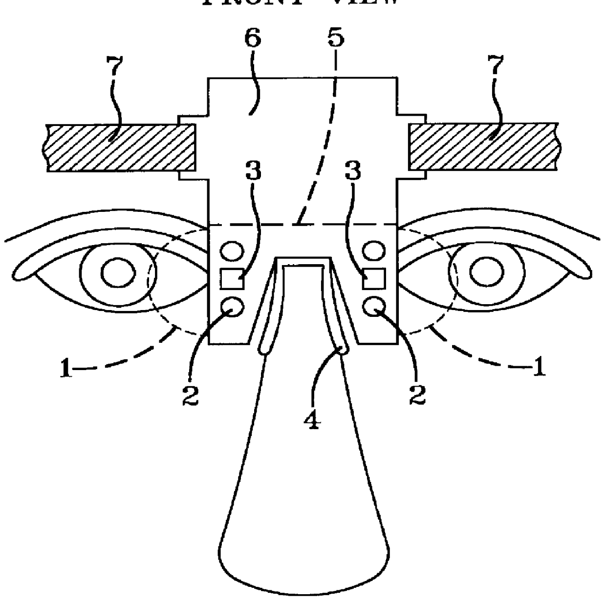
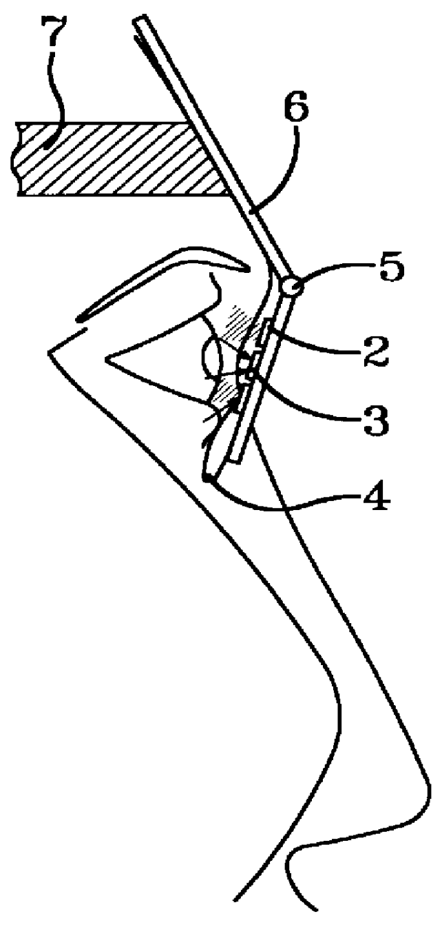
The preferred embodiment of the presently disclosed eye movement measuring device is comprised of an adjustable mounting structure, sensing means, and measurement calculation means FIGS. 1A and 1B. The device is adaptable to and capable of utilizing multiple kinds of sensing technology.

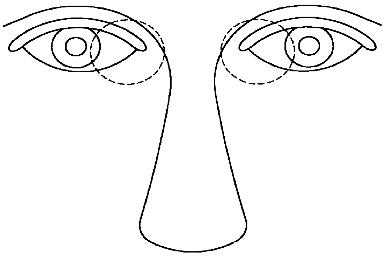
The adjustable mounting structure is comprised of a nose bridge component FIG. 1A4, a forehead plate FIG. 1A6, adjustment means FIG. 1A5, and an adjustable head strap FIG. 1A7. The nose bridge component FIG. 1A4, which is similar to the bridge support on common eye glasses, rests on the user's nose. The proprietary design of the nose bridge and forehead plate FIG. 1A6 minimally obstructs the user's field of vision, whereby, the only portion of the user's visual range which is obstructed is slightly more than what the user's own nose would obstruct FIG. 1A. Thus, a wider variety of tests can be performed on the user than with the prior art devices. The forehead plate FIG. 1A6 extends above the nose br...


PUM


Abstract

The presently disclosed invention is a device for measuring horizontal and vertical eye movement. The device is adaptable to utilize multiple measurement technologies (e.g., direct infrared, electro-oculography, ultrasound, or video), and is capable of measuring each eye individually or both eyes jointly. The present invention overcomes the shortcomings of the prior art by requiring minimal adjustment for accurate measurement, only minimally obstructing the user's visual range (i.e., slightly more than the user's own nose), being made of low cost and readily available material, and by being comprised of a comfortable and efficient design of an adjustable nose and forehead piece with an adjustable head strap. An additional advancement over the prior art is that the presently disclosed device does not require an aperture or frame, as did the prior art, or any additional optics such as, lenses, mirrors, or prisms. The device rests on the user's nose with the sensors located near the nasal area of the eye(s) utilizing a nose bridge component to house the measuring technology. The forehead piece and head strap provide for ease of alignment, added stability, and a wide range of test applications. The greater field of vision provided by this device allows for a wide range of test applications.

Description

In devices used for measuring eye movement, the prior art required precise adjustments for each subject, and complete to partial blocking of the subject's visual range which detrimentally inhibited testing capabilities. Certain versions of these devices limited the subject's mobility by requiring the subject to remain perfectly still during measurement. These prior devices were designed to be worn as goggles, helmets, or spectacles which housed the measurement technology.The main types of eye movement measurement and monitoring systems in common use are: Infrared; Video; Electro-oculography; Limbus trackers; Purkinje reflection trackers, and Scleral Coil trackers. Limbus trackers are generally cheap and easy to use, but mainly only useful for measurements in one axis at a time, that is, they are not gaze monitors. For accurately assessing point of gaze the most common method is the video tracker, where the pupil or iris is imaged using a video camera and a simple image processing mo...

Claims


Application Information

Patent Timeline
IPC IPC(8): A61B3/113A61B5/00A61B8/00
CPCA61B3/113A61B5/0059A61B8/00
Inventor OBER, JAN KRZYSZTOFOBER, JAN JAKUB
Owner BERTEC
Why Eureka
Try Eureka