Coating unit

a technology of coating unit and coating film, which is applied in the direction of valves, mechanical devices, operating means/releasing devices, etc., can solve the problems of easy deterioration of the quality of the treatment body, change of coating film, and difficulty in accurately controlling the time for opening and closing the valv

Inactive Publication Date: 2000-09-05
TOKYO ELECTRON LTD
View PDF12 Cites 44 Cited by
  • Summary
  • Abstract
  • Description
  • Claims
  • Application Information

AI Technical Summary

Problems solved by technology

Due to the aforementioned dripping and bubbles, thickness of a coating film changes and the quality of a treatment body easily deteriorates.
Accordingly, operation is accompanied by delay time so that it is difficult to accurately control the time for working an opening and closing valve.
Mor

Method used


Image

  • Coating unit
  • Coating unit
  • Coating unit

Examples


Embodiment Construction

The preferred embodiment of the present invention will now be described in detail with reference to the drawings.

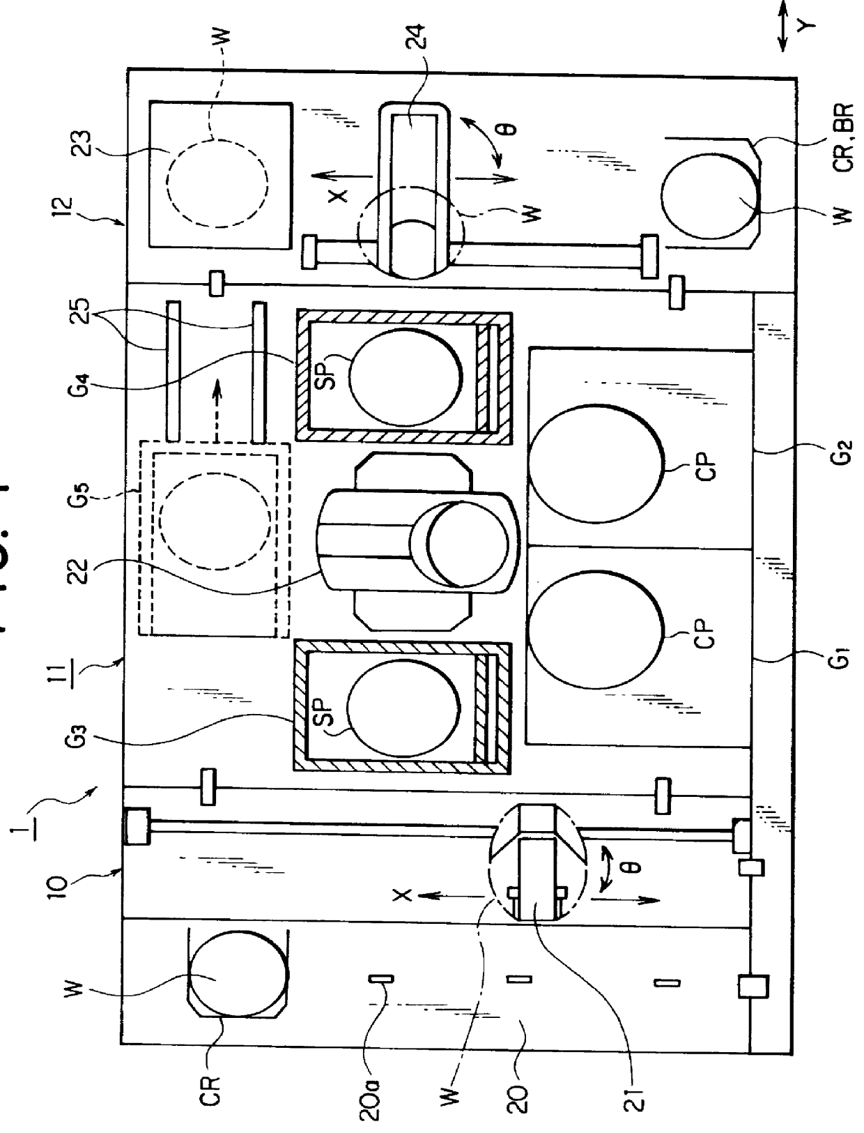
FIG. 1 is a plane view showing an entire coating and developing system 1 for a semiconductor wafer (referred to as "a wafer" hereinafter) provided with a resist coating unit (COT) according to an embodiment of the present invention.

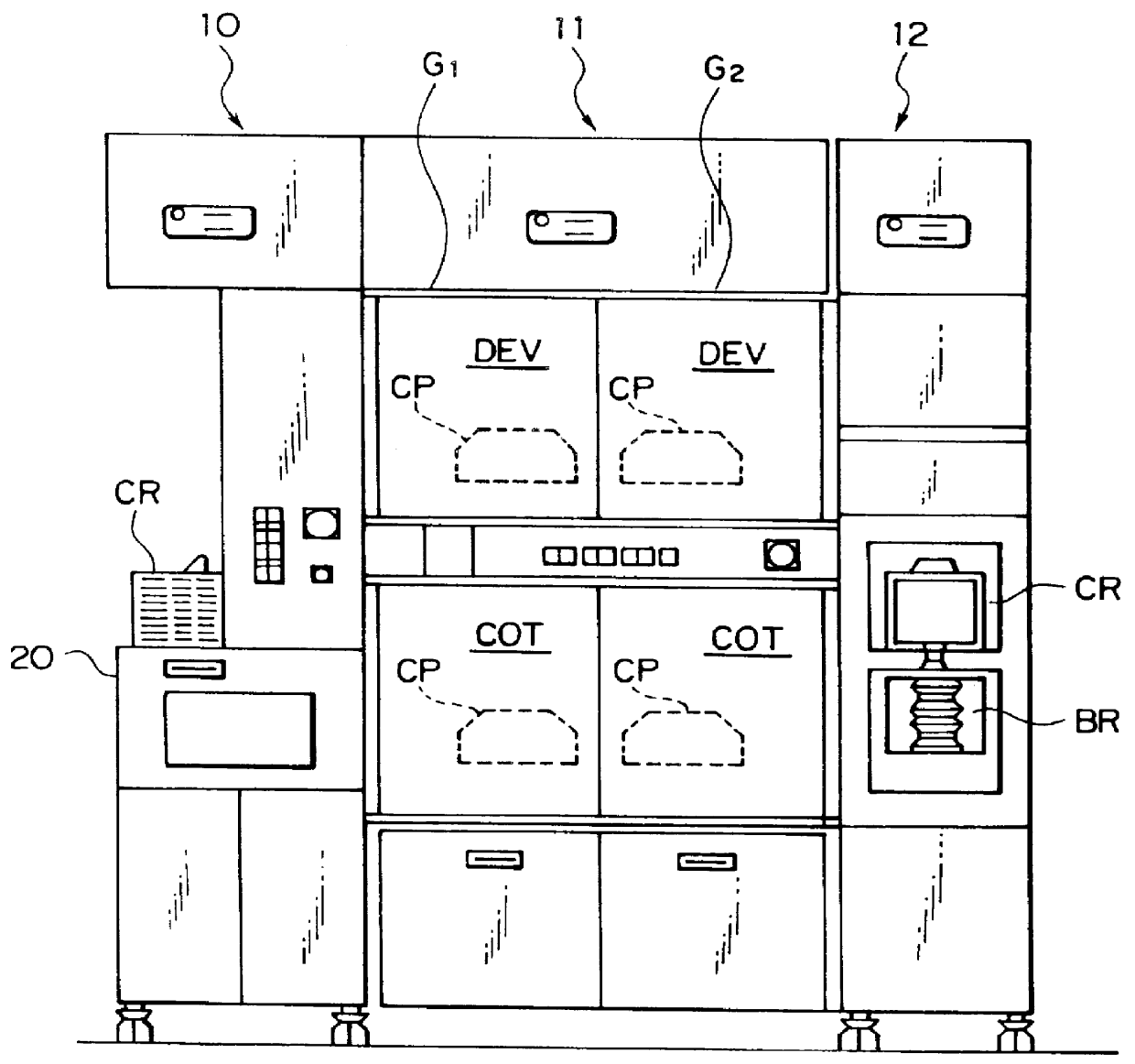
In the coating and developing system 1, a cassette station 10, a treatment station 11, and an interface unit 12 are integrally connected. In the cassette station 10, plural wafers W as treatment bodies, for example, twenty-five wafers per wafer cassette CR are transferred to / from the system from / to the outside, and the wafer W is transferred to / from the wafer cassette CR.

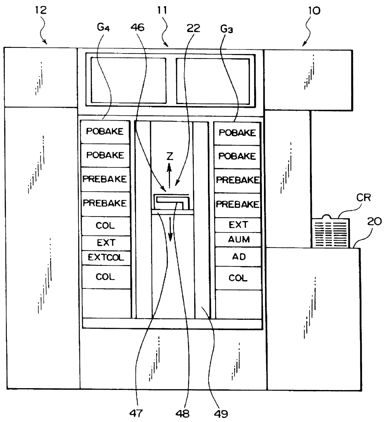
In the treatment station 11, various kinds of treatment units are multi-tiered in the predetermined position. Each treatment unit performs the predetermined treatment for wafers W one by one in a coating and developing process.

In the interface unit 12, the wafer W is sent and r...


PUM


Abstract

In a coating unit, a piezovalve driven by piezoelectric elements is used as an opening and closing valve 79. The use of the piezovalve which can nearly disregard delay time makes it possible to accurately control the time of working the opening and closing valve 79 and to finely control working speed thereof at the time of opening and closing the valve. Therefore, operation necessary for closing the valve can be slowly performed, thus appropriately preventing dripping of a resist solution and occurrence of bubbles in a resist solution by air which enters from a forward end of a resist nozzle 60.

Description

1. Field of the InventionThe present invention relates to a coating unit for coating a surface of a treatment body such as a semiconductor wafer with a coating solution such as a resist solution.2. Description of the Related ArtIn a photolithography process of semiconductor device fabrication processes, for example, first, a resist coating treatment is performed to form a resist film on a surface of a semiconductor wafer (referred to as "a wafer" hereinafter) Next, after being resist-coated, the wafer is exposed and then developed.A coating unit for performing a resist coating treatment is now taken up. A conventional coating unit has a structure shown in FIG. 18. Specifically, a resist solution kept in a resist tank 201 is pressed out to a nozzle with a pump 202. Meanwhile, timing for discharging the resist solution from a nozzle 205 is controlled by opening and closing a flow path of the resist solution with a valve 204 disposed between the pump 202 and the nozzle 205.FIG. 19 is a...

Claims


Application Information

Patent Timeline
IPC IPC(8): B05C11/10F16K31/00H01L21/00B05C11/08H01L21/027
CPCB05C11/1026B05C11/1047F16K31/004H01L21/6715B05C11/08H01L21/30
Inventor FUJIMOTO, AKIHIRO
Owner TOKYO ELECTRON LTD
Why Eureka
Try Eureka