Tilt detecting device

a detection device and tilt technology, applied in the direction of instruments, contacts, surveying lines, etc., can solve the problems of high production cost, large number of members of the tilt detection device, and complicated structur

Inactive Publication Date: 2000-09-12
CASIO COMPUTER CO LTD
View PDF14 Cites 19 Cited by
  • Summary
  • Abstract
  • Description
  • Claims
  • Application Information

AI Technical Summary

Problems solved by technology

However, according to the conventional tilt detecting device, there are problems that the tilt detecting device requires a large number of members and a complic

Method used


Image

  • Tilt detecting device
  • Tilt detecting device
  • Tilt detecting device

Examples


first embodiment

The first embodiment of the tilt detecting device in accordance with the present invention will be explained with reference to FIGS. 1 to 6.

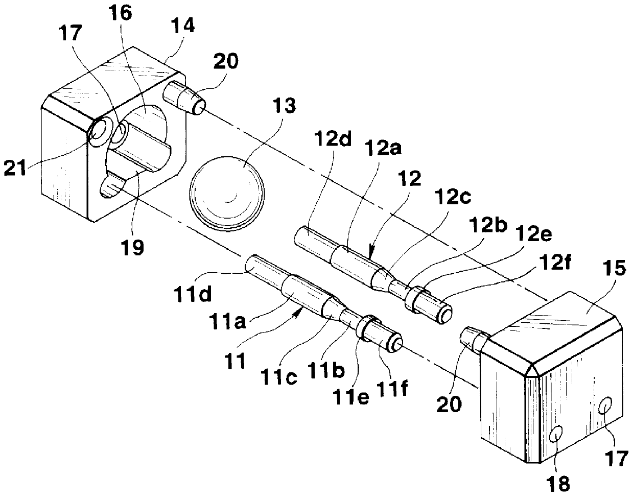
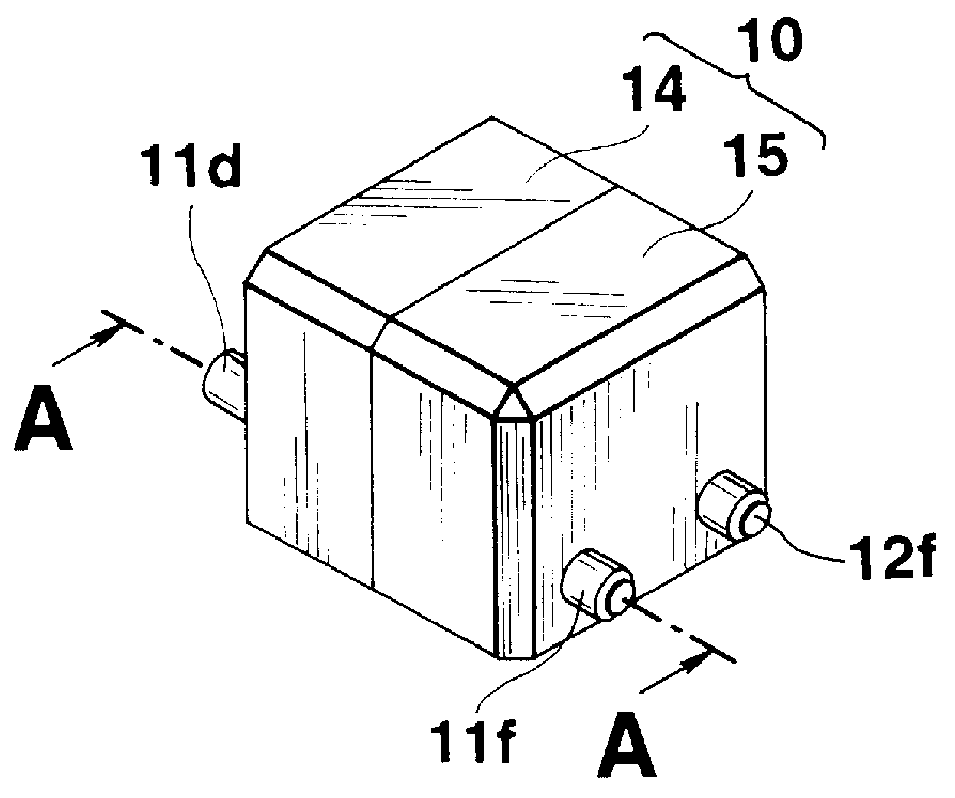
FIG. 1 is a perspective view of the tilt detecting device, and FIG. 2 is an exploded perspective view thereof.

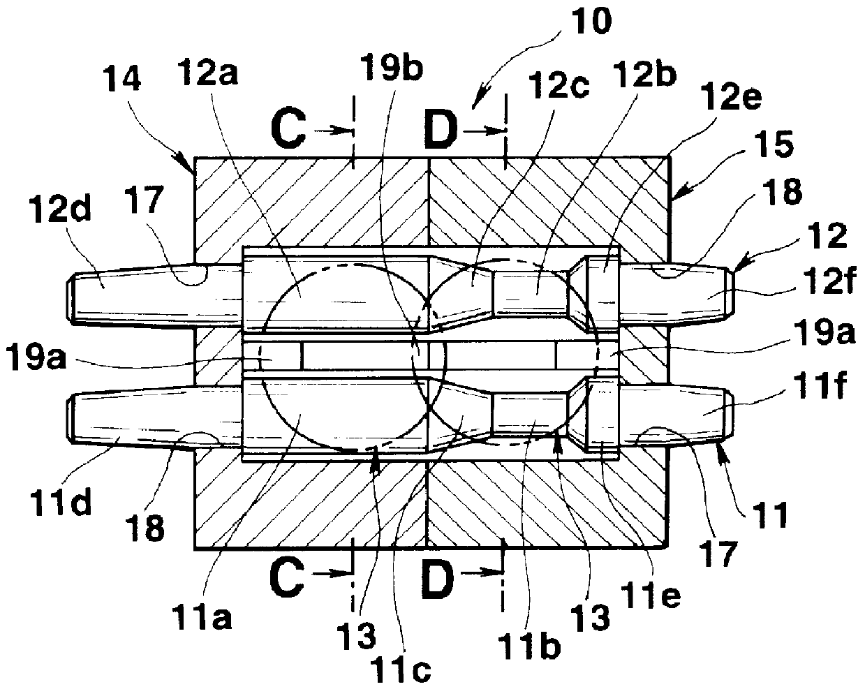
The tilt detecting device comprises an insulation case 10, two conductive pins 11 and 12 disposed in the insulation case 10, and a conductive ball 13 which is movable in the insulation case 10 along in a longitudinal direction of the two conductive pins 11 and 12 when the insulation case 10 is inclined.

Each of the two conductive pins 11 and 12 is made of a conductive material such as a metal or the like and has a large diameter portion 11a and 12a and a small diameter portion 11b and 12b, respectively. In each of the two conductive pins 11 and 12, a tapered portion 11c and 12c is formed between the large diameter portion 11a and 12a and the small diameter portion 11b and 12b, a large diameter side attachment portion lid and 12d is formed...

second embodiment

Next, a second embodiment of the tilt detecting device in the invention will be explained with reference to FIGS. 8 to 15. To structural members or the like corresponding to those of the first embodiment shown in FIGS. 1 to 6, the same reference numerals are attached, and the detailed explanation for them is omitted.

The tilt detecting device comprises the insulation case 10, two conductive pins 25 and 26 disposed in the insulation case 10, and the conductive ball 13 which is movable in the insulation case 10 to be in contact with or separated from the two conductive pins 25 and 26 when the insulation case 10 is inclined, as shown in FIGS. 8 and 9.

Each of the two conductive pins 25 and 26 is made of the conductive material such as a metal or the like and which has large diameter portions 25c and 26c, a small diameter portion 25a and 26a in each intermediate portion, a head portion 25b and 26b in each upper end portion, and a tapered lower end portion.

case 10

The insulation case 10 comprises a first case 27 and a second case 28 which are the top and bottom portions of the insulation case 10 when the insulation case 10 is divided in the vertical direction. The first and second cases 27 and 28 are made of the insulating material such as a synthetic resin or the like and formed in absolutely the same shape as each other, like the first embodiment.

As shown in FIG. 10A, the cases 27 and 28 have concavities 27b and 28b at surfaces 27a and 28a faced to each other, and the concavities 27b and 28b have bottom surfaces 27c and 28c, respectively.

The containing portion 16 is formed in an interior of the second case 28 which is the lower side of the insulation case 10. An upper surface side of the containing portion 16, which faces to the first case 27 is opened, as shown in FIG. 9. In a bottom portion of the second case 28, a recess portion 29 in which the conductive ball 13 is contained is formed, as shown in FIG. 10A. In a right side of the bottom...


PUM


Abstract

A tilt detecting device for use in various electronic apparatuses such as a watch, electronic notebook or the like. The tilt detecting device includes a projection in a part of a ball containing portion formed in an interior of an insulation case. In the insulation case, two conductive pins are disposed thereon in parallel with each other with a predetermined space, which have a large diameter portion, a small diameter portion and a step between them. In the ball containing portion, a conductive ball is contained therein, which is movable along in a longitudinal direction of the two conductive pins in the ball containing portion when the insulation case is inclined. Only when the insulation case is inclined, the conductive ball is at a position on the large diameter portions to be electrically in contact with the two conductive pins to output a corresponding detection signal.

Description

1. Field of the InventionThe present invention relates to a tilt detecting device.2. Description of the Related ArtConventionally, an electronic watch which has a tilt detecting device incorporated in a case, wherein the tilt detecting device detects an inclination of the case, only when a person moves the one's arm to the front of the one and inclines the arm to the one's side, to display a display portion, e.g., a liquid crystal display device or the like for displaying the time and the like by lighting it according to a detection signal, has been known.In such a tilt detecting device, when the case is held horizontally, a conductive ball incorporated therein is not electrically in contact with a pair of conductive members incorporated in the case so as not to output a corresponding detection signal, while when the case complete is inclined, the conductive ball is electrically in contact with both of the pair of conductive members so that the pair of conductive members are electri...

Claims


Application Information

Patent Timeline
IPC IPC(8): G01C9/10G01C9/00H01H35/02G01C9/06G01B7/30G04G99/00
CPCG01C9/10H01H35/02G01C2009/068G01C2009/107H01H2001/5888H01H2011/0081H01H2011/065G01B7/30G04G99/00G01C9/00
Inventor TANAZAWA, MASAYOSHIMINAMI, SHUNJI
Owner CASIO COMPUTER CO LTD
Why Eureka
Try Eureka