Turbine passive thermal valve for improved tip clearance control

Inactive Publication Date: 2000-09-12
PRATT & WHITNEY CANADA CORP
View PDF19 Cites 62 Cited by
  • Summary
  • Abstract
  • Description
  • Claims
  • Application Information

AI Technical Summary

Benefits of technology

Another feature of the present invention is to provide a method of controlling the clearance between the tips of a stage of turbine blades and a surrounding annular casing and associated shroud segment assembly of a gas turbine e...

Problems solved by technology

Further, the passive thermal valve arrangement...

Method used


Image

  • Turbine passive thermal valve for improved tip clearance control
  • Turbine passive thermal valve for improved tip clearance control
  • Turbine passive thermal valve for improved tip clearance control

Examples


Embodiment Construction

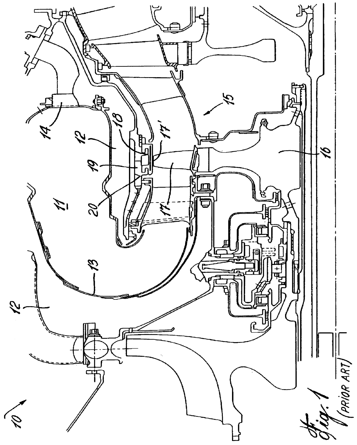
Referring now to the drawings and more particularly to FIG. 1, there is shown generally at 10 the combustion and high pressure turbine sections of a gas turbine engine of the prior art. The combustion section includes a combustion chamber 11 in which compressor air from the surrounding chamber 12 is admitted through its perforated wall 13 to mix with the fuel entering through the nozzle 14 to create a combustible mixture. This hot gas combustion is usually at temperatures exceeding 2000.degree. F. and is fed into the turbine section 15 where one or more stages 16 of rotor blades 17 are mounted. As hereinshown the tip end 17' of the rotor blade 17 is positioned in close spacing with an annular shroud segment assembly 18. The shroud segment assembly 18 is supported by an annular casing 19. The annular casing 19 is provided with through bores 20 or channels to admit cooling air from the surrounding chamber 12 thereabout and in the area of the annular shroud segment assembly 18 to cool ...


PUM


Abstract

A gas turbine engine blade tip clearance control system and method is described. An annular housing is formed about an engine casing to which an annular shroud segment assembly is secured and closely spaced about blade tips of a stage of blades. The annular housing forms an air passage means communicating with the casing for directing a cooling air stream to the casing. A thermally operable passive ring valve is formed by two overlapped metal ring segments having a dissimilar coefficient of thermal expansion selected whereby to produce a radial gap between the ring segments when the valve temperature reaches a predetermined value. The radial gap admits a cooling air flow into the housing for cooling the casing and its associated shroud segment assembly to control radial growth and thereby prevent blade tip pinching.

Description

The present invention relates to a gas turbine engine blade tip clearance control system and method utilizing a thermally operable passive valve whereby to control radial growth of the shroud segment support casing at low and high power settings of the engine.The present invention is directed at remedying the problem in gas turbine engines wherein the tips of the turbine blades of the engine penetrate the linings of the shroud segments which surround them and thereby destroy the desired clearance therebetween with resulting loss in efficiency in certain flight conditions. Various attempts have been made at remedying the problem of controlling radial growth of the casing about the turbine blades during take-off and other transient operating conditions of the engine where the difference between blade tip and casing growth is greater. During transient conditions it is desirable to keep the casing hot whereas in steady state conditions, it is desired to cool the casing.Former solutions ...

Claims


Application Information

Patent Timeline
IPC IPC(8): F01D11/24F01D11/08F01D11/18
CPCF01D11/18F01D11/24
Inventor PIERRE, SYLVAINDOBSON, MARTIN JOHN
Owner PRATT & WHITNEY CANADA CORP
Why Eureka
Try Eureka