Method and apparatus for controlling cooling and heating fluids for a gas distribution plate

Inactive Publication Date: 2000-09-12
APPLIED MATERIALS INC
View PDF15 Cites 245 Cited by
  • Summary
  • Abstract
  • Description
  • Claims
  • Application Information

AI Technical Summary

Benefits of technology

The invention generally provides an apparatus and a method of regulating the temperature of a component of a substrate processing chamber to provide consistent substrate pr

Problems solved by technology

A uniform distribution of gas concentration within the processing chamber is highly desirable to ensure a uniform progression of the process because variations in the gas concentration within the process chamber produce non-uniform deposition across the substrate surface resulting in a non-planar topography which can lead to reduced yield and device failure.
If deposition occurs on the showerhead, it may clog the showerhead holes and disturb the process gas distribution into the chamber, causing uneven processing on the substrate surface, or particulates of the deposition material can flake off from the showerhead and drop onto the substrate surface, rendering the substrate useless.
Furthermore, improper temperature of the gas delivery system may cause condensation of the process gas within the gas delivery system, and reduce the amount of
process gas reaching the process chamber and resulting in inadequate deposition.
Typically, because of the low pressures present in CVD processing, the emmisivity of the gas distribution plate is the primary contributor affecting the substrate temperature.
One particular drawback of the BCS method is the "first wafer effect" in which the first few wafers are rendered useless because of temperature inconsistencies which lead to non-uniform processing results between wafers.
The inconsistent properties of the film deposited on the first few wafers, as compared to those processed during steady state conditions, renders the first few wafers useless.
Temperature

Method used


Image

  • Method and apparatus for controlling cooling and heating fluids for a gas distribution plate
  • Method and apparatus for controlling cooling and heating fluids for a gas distribution plate
  • Method and apparatus for controlling cooling and heating fluids for a gas distribution plate

Examples


Embodiment Construction

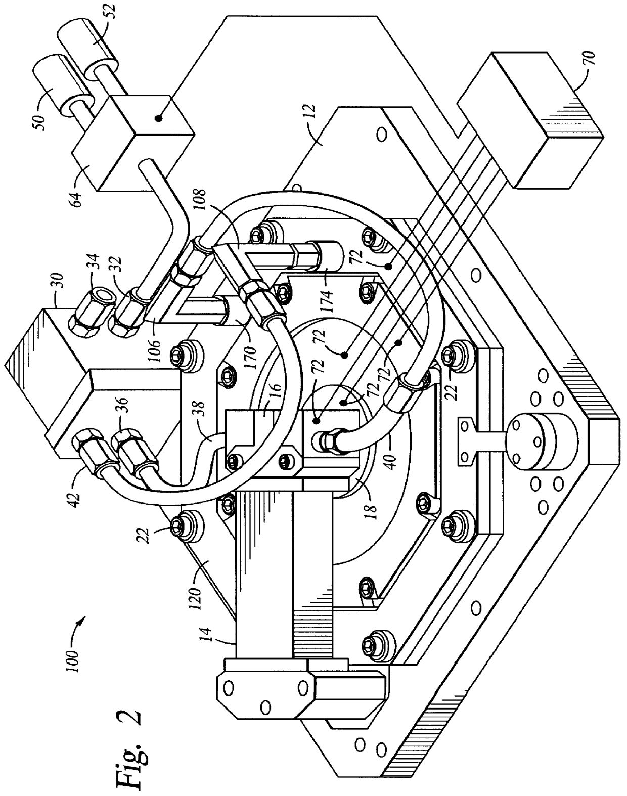
FIG. 2 is a perspective view of a CVD chamber lid having a temperature control system of the invention. The lid 100 generally includes a base plate 12, a process gas injection manifold 14 and a gas distribution plate 120 secured therebetween. The base plate 12 is preferably releasably secured to the top portion of the CVD chamber (not shown) and seals the processing environment during processing.

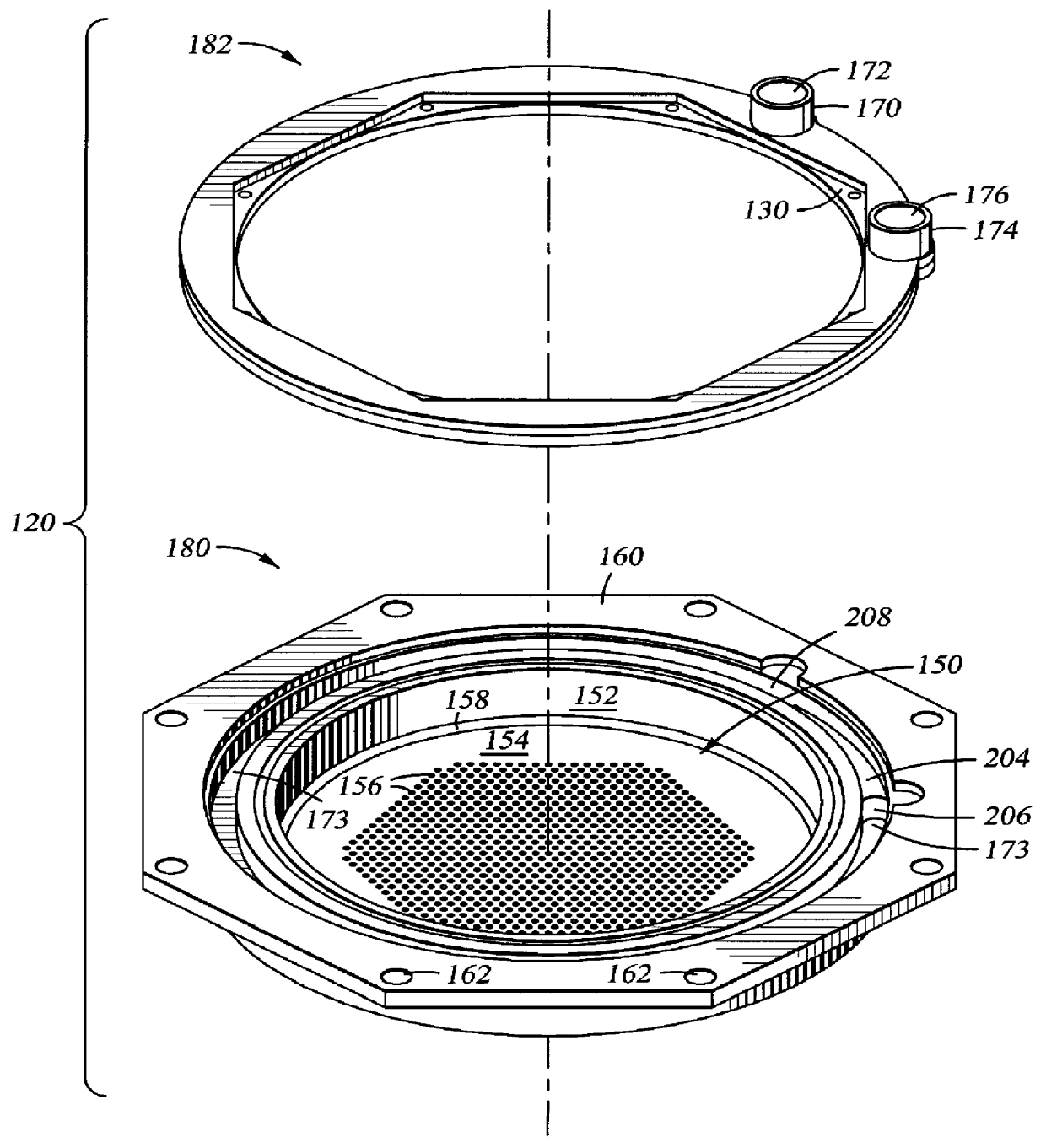
Referring to both FIG. 1 and FIG. 2, the gas distribution plate 120 is secured and sealed to the base plate 12 by fasteners 22 and generally includes a thermal fluid passage cover 182 and a base 180 having a thermal fluid passage 173. The thermal fluid passage cover 182 includes a thermal fluid inlet 170 forming the inlet of the thermal fluid passage 173 and a thermal fluid outlet 174 forming the outlet of the thermal fluid passage 173. The base 180 includes a cavity 150 defined by side wall 152 and bottom plate 154 which includes a plurality of gas distribution holes 156 to provide process ...


PUM

PropertyMeasurementUnit
Temperatureaaaaaaaaaa
Electrical conductoraaaaaaaaaa
Heataaaaaaaaaa

Abstract

The invention provides an apparatus and a method of regulating temperature of a component of a processing chamber comprising providing a thermal conductor thermally connected to the component, providing a controller connected to the thermal conductor, providing at least one temperature sensor connected to the component to supply temperature readings to the controller and regulating heat transfer between the component and the thermal conductor by changing the temperature of the thermal conductor. The invention also provides an apparatus and a method for providing a thermal gradient in a chamber component comprising providing a first thermal conductor at a first temperature attached to the component and providing a second thermal conductor at a second temperature attached to the component.

Description

BACKGROUND OF THE INVENTION1. Field of the InventionThe present invention generally relates to substrate processing chambers. More particularly, the present invention relates to controlling the temperature of a component of a substrate processing chamber.2. Background of the Related ArtIn the fabrication of integrated circuits, vacuum process chambers are generally employed to deposit films on semiconductor substrates. The processes carried out in the vacuum chambers typically provide the deposition or etching of multiple metal, dielectric and semiconductor film layers on the surface of a substrate. Examples of such processes include chemical vapor deposition (CVD), physical vapor deposition (PVD), and etching processes. For CVD, a variety of gases are introduced into the process chamber and act as reactants which deposit material on the substrate surface. A uniform distribution of gas concentration within the processing chamber is highly desirable to ensure a uniform progression of...

Claims


Application Information

Patent Timeline
IPC IPC(8): H01J37/32C23C16/42H01L21/205
CPCH01J37/3244H01J37/32522H01J37/32
Inventor MANDREKAR, TUSHARTOLIA, ANISHKHURANA, NITIN
Owner APPLIED MATERIALS INC
Why Eureka
Try Eureka