Projection-type display apparatus

a display device and projection type technology, applied in the field of projection type display devices, can solve the problems of color unevenness, degraded display quality, and inability to ignore the lowering

Inactive Publication Date: 2000-09-19
SEIKO EPSON CORP
View PDF22 Cites 33 Cited by
  • Summary
  • Abstract
  • Description
  • Claims
  • Application Information

AI Technical Summary

Benefits of technology

Another object of the present invention is to provide an inexpensive projection-type display apparatus which can generate a projection image of high quality.
According to such constitution, since the cooling means is located on the reverse side to a viewer of a projection image, it is advantageous in preventing noises and exhausted air from the cooling means from disturbing the viewer.

Problems solved by technology

However, when the pixel pitch is small, for example, as in a liquid crystal panel using a polysilicon TFT as a switching device, such lowering cannot be ignored.
Therefore, if the initial brightness distribution is not axially symmetrical, color unevenness arises in the display on a screen, and the quality of the display is degraded.
This results in color unevenness and a change in color temperature of a projected image.
Therefore, a sufficient effect of the optical integrator cannot be shown.
Furthermore, when the optical integrator is used in the light source portion, the conventional art cannot be utilized as it is.

Method used


Image

  • Projection-type display apparatus
  • Projection-type display apparatus
  • Projection-type display apparatus

Examples


first embodiment

Advantage of First Embodiment

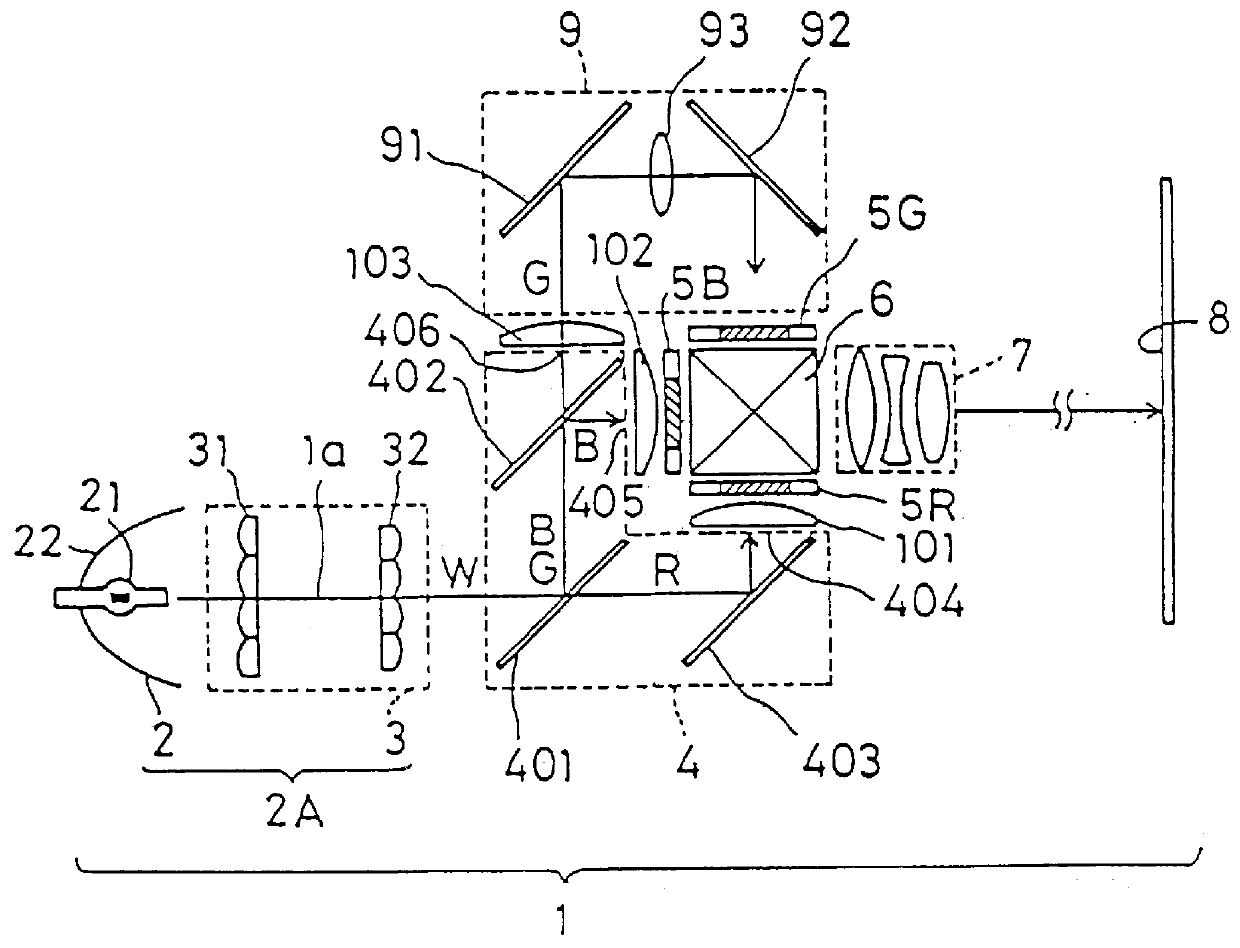
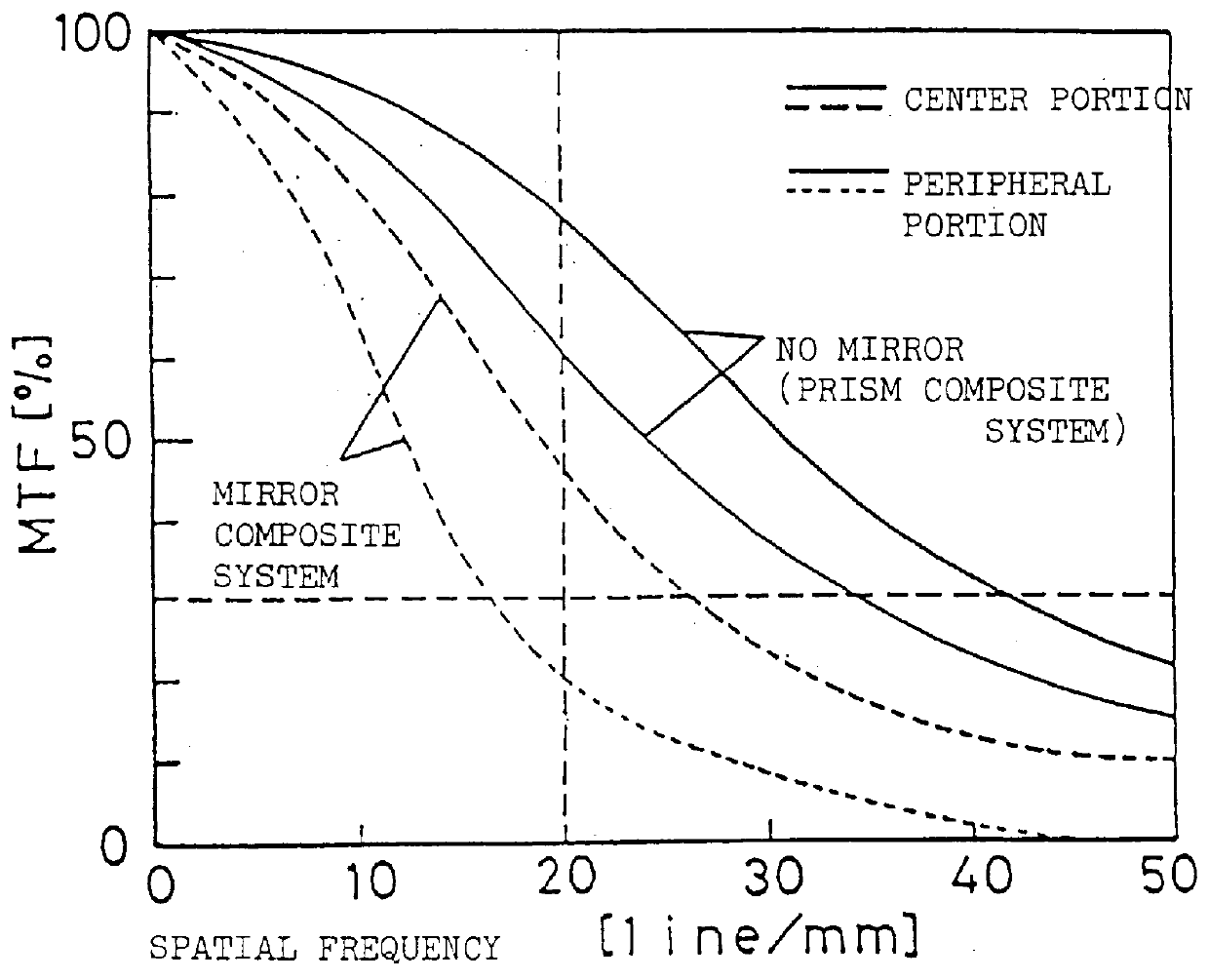
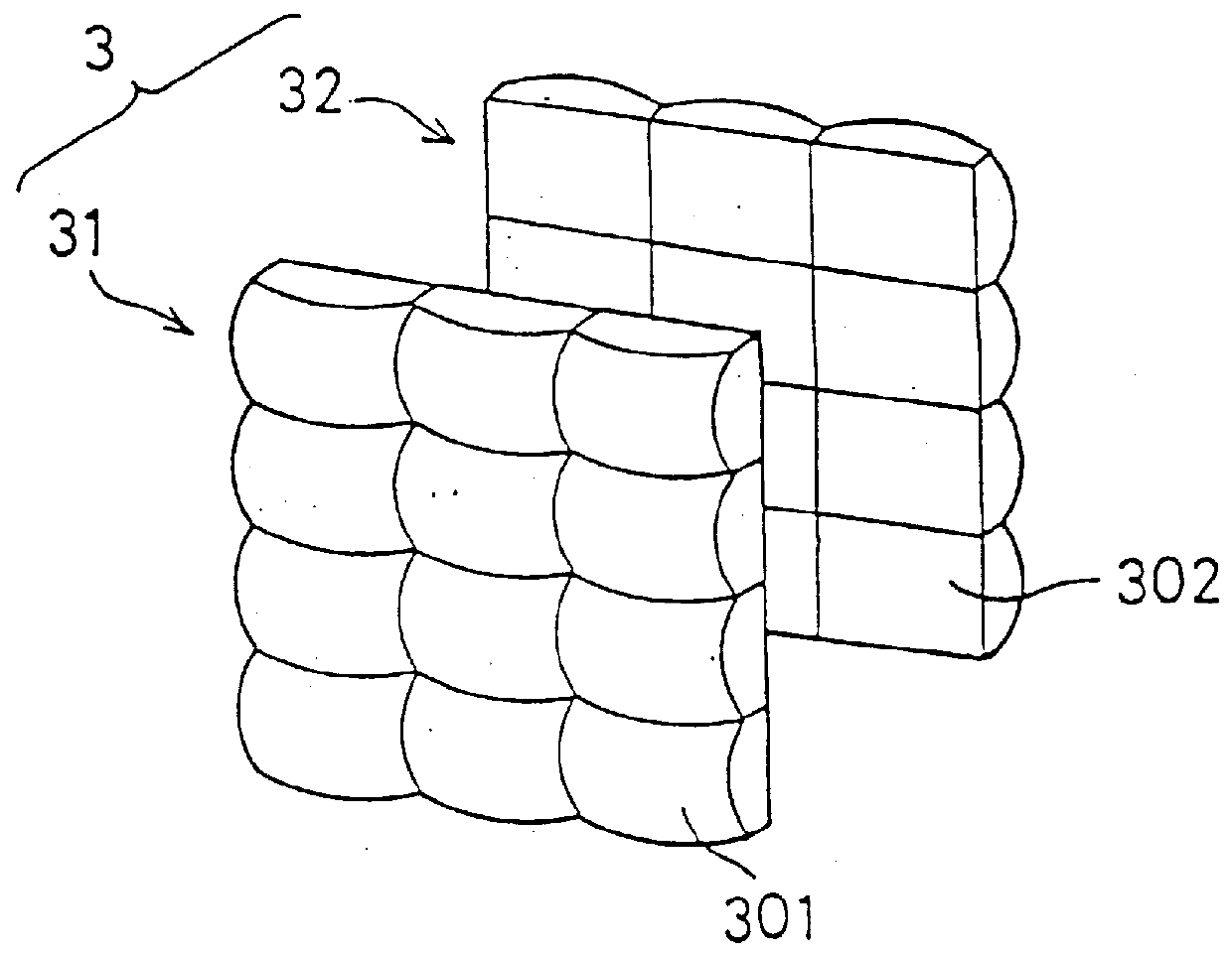
As described above, in the projection-type display apparatus 1 of this embodiment, the employed illumination optical system is provided with the uniform illumination optical device 3, and a dichroic prism, which is an axially symmetrical optical device, is used as the color synthesizing optical system. Therefore, it is possible to realize a projection-type display apparatus in which unevenness in color and luminous intensity is small and the illumination efficiency is high. Furthermore, since the color synthesizing system including a dichroic prism is used, the focal length of the projection lens can be shortened, and a large-scale display at a short distance can be performed. Consequently, the application of the constitution of this embodiment to a rear projector makes it possible to shorten the depth of the projector, and to make the projector compact.

Furthermore, since the focal lengths of the intermediate lens, the incident lens and the outputting le...

second embodiment

FIG. 10(A) illustrates a projection-type display apparatus according to a second embodiment of the present invention. A projection-type display apparatus 100 in this embodiment is the same as the above-mentioned projection-type display apparatus 1 in the first embodiment except for the structure of a light guide system. Therefore, like components are denoted by like numerals, and the explanation thereof is omitted.

A light guide system 9E in the projection-type display apparatus 100 of this embodiment is constituted by an incident side triangular prism 901, an output side triangular prism 902 and a quadratic prism 903 located between the triangular prisms 901 and 902.

The operation of the light guide system 9E in this embodiment will be described with reference to FIG. 10(B). A light beam collimated by the condenser lens 103 vertically enters an incident plane 904 of the triangular prism 901, is reflected by a total reflection plane 905, and output from an outputting plane 906. The to...

third embodiment

FIG. 14(A) illustrates a projection-type display apparatus according to a third embodiment of the present invention. A projection-type display apparatus 500 in this embodiment is the same as the above-mentioned one of the first embodiment, except for the structure of a light guide system thereof. Therefore, like components are denoted by like numerals, and the explanation thereof is omitted.

A light guide system 9F in the projection-type display apparatus 500 of this embodiment is comprised of a field lens 921 which acts as an incident lens on the incident side, a field lens 922 which acts as an incident lens on the output side and a concave mirror 923. A condenser lens 103 adjacent to the incident portion of the light guide system 9F and the field lens 921 may be combined into a single lens.

A light guide system 9G having such structure is illustrated in FIG. 14(B). An integrally formed lens 924 consists of a decentered double-convex lens as illustrated.

A concrete structure of the ab...


PUM


Abstract

A projection-type display apparatus includes a light source, a uniform illumination optical system, a color separating system for separating a white light beam emitted from the uniform illumination optical system into three color beams, three liquid crystal panels for respectively modulating each of the separated color beams, a light guide system located on an optical path of the color beam having the longest optical path among the separated color beams, a dichroic prism for synthesizing the beams modulated through the liquid crystal panels, and a projection lens for projecting the synthesized and modulated beam onto a screen. The uniform illumination optical system is provided with a uniform illumination optical device for converting the white light beam emitted from the light source into a uniform beam. Since the dichroic prism, which is an optical element that is rotationally symmetrical about the chief axis of a projection optical system, is employed as a color synthesizing system, and the uniform illumination optical device for restricting unevenness in color and luminous intensity is incorporated in the system, it is possible to realize a display apparatus which causes little unevenness in color and luminous intensity and which has a high illumination efficiency.

Description

The present invention relates to a projection-type display apparatus which separates a white beam from a light source into beams of three colors, red, blue and green, modulates these beams through light valves according to image information, and re-synthesizes and projects the modulated beams under magnification onto a screen through a projection lens.DESCRIPTION OF THE RELATED ARTA projection-type display apparatus is comprised of a light source lamp, a color separating means for separating a white beam from the light source lamp into beams of three colors, three light valves for modulating the separated color beams, a color synthesizing means for synthesizing the modulated beams again, and a projection lens for magnifying and displaying a light image obtained by the synthesis onto a screen. As light valves, liquid crystal panels are generally used.A conventional projection-type display apparatus having such structure in which a uniform illumination optical device referred to as an...

Claims


Application Information

Patent Timeline
Patent Type & Authority Patents(United States)
IPC IPC(8): G03B21/20G03B21/14G03B33/12H04N5/74H04N9/31
CPCG02B3/0043G02B3/005G02B3/0056G02B3/0062G03B33/12H04N9/3105H04N9/3167H04N9/3197G03B21/208H04N5/7441
Inventor NAKAYAMA, TADAAKIITOH, YOSHITAKAYAJIMA, AKITAKA
Owner SEIKO EPSON CORP
Why Eureka
Try Eureka